Scene 1 (0s)
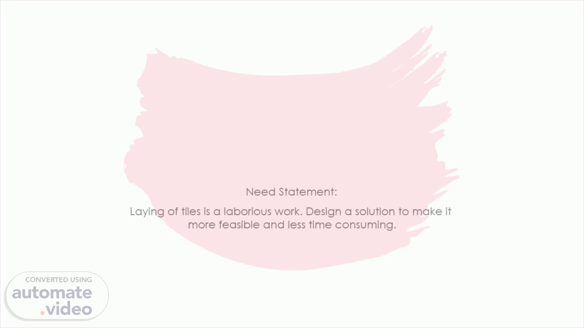
[Audio] TILE LAYING MACHINE. Need Statement. Laying of tiles is a laborious work. Design a solution to make it more feasible and less time consuming..
Scene 2 (14s)
[Audio] Problem Definition. A tile laying machine is an instrument which is used flatten sand and lay various types of tiles on a designated floor. These types of bots are programmable and are able to dispense required material when necessary..
Scene 3 (33s)
[Audio] Objectives. User friendly. Strong framework/Durable. Bot should be as light as possible. Bot should be portable. Sturdy material. Aesthetically pleasing. Good gripped tire. Problem definition 1.1. Design a user friendly tile laying machine, that is light and portable. The bot must be made up of sturdy material and have a strong framework to support the entire system. It should have a good gripped tire in order to facilitate it's movement. It should also be aesthetically pleasing to the eyes of an observer..
Scene 4 (1m 19s)
[Audio] Constraints. Problem definition 1.2. Design a user friendly tile laying machine, that is light and portable. The bot must be made up of sturdy material and have a strong framework to support the entire system. It should have a good gripped tire in order to facilitate it's movement. It should also be aesthetically pleasing to the eyes of an observer. The bot should be 3x3x3 feet in dimensions and should be built within a budget of 5000 INR within a time duration of 2 months. It should be able to hold 10 tiles of size 1.5x.5 feet of standard thickness..
Scene 5 (2m 5s)
[Audio] Problem definition 1.3.Design a user friendly tile laying machine, that is light and portable. The bot must be made up of sturdy material and have a strong framework to support the entire system. It should have a good gripped tire in order to facilitate it's movement. It should also be aesthetically pleasing to the eyes of an observer. The bot should be 3x3x3 feet in dimensions and should be built within a budget of 5000 INR within a time duration of 2 months. It should be able to hold 10 tiles of size 1x1 feet of standard thickness. The bot should have a provision to turn on and off with a switch and should have an indicator, which shows that the bot is operational. It should be able to store and lay tiles while the bot is in motion..
Scene 6 (2m 59s)
SL NO 2 3 4 5 6 7 8 9 10 11 12 13 14 15 QUESTION What is the budget? What kind of a power source do want the bot to use? What's the size of the machine? Should the machine be user friendly? Do you want a switch on the machine? Should the machine be Durable? How heavy do you want the machine? Do you want the machine to be portable? Do you want an indication for when it's working? What should the size of I tile be? How many tiles do you want it to lay in one cycle? What material should be used to make the machine? Do you want a compartment to store tiles? Do you want the machine to be slip proof. Should the machine be aesthetically pleasing? ANSWERS 5000 Rs power socket 3x3x3 feet Yes Yes Yes As light as possible Yes Yes I .5xI.5 foot 10 tiles Any sturdy material Yes Yes Yes OBJECTIVE Yes Yes Yes Yes Yes Yes Yes FUNCTION Yes Yes Yes CONSTRAINT Yes Yes Yes Yes Yes.
Scene 7 (3m 29s)
Concept generation:. ESTABLISHING FUNCTIONS :. SL.NO 1 2 3 4 FUNCTIONS FROM USER PERSPECTIVE Movement of bot Laying of tiles FUNCTIONS FROM DESIGNER PERSPECTIVE Flattening the sand Storing tiles Mechanism to dispense tiles Movement of bot.
Scene 8 (3m 41s)
Function Tree:. Screenshot (158).
Scene 9 (3m 47s)
Morphological chart:. SL.NO 1 SUBFUNCTIONS Conversion of Mechanical energy to Kinetic Energy MEANS 1 V-belt pulley wheels MEANS 2 Belt Drive MEANS 3 MEANS 4 Omni VVheels.
Scene 10 (3m 58s)
Crankshaft Pushing of the tiles 3 on to conveyer belt.
Scene 11 (4m 8s)
00 5 6 Switching on the bot Storage of tiles Vertical columns on off switch Box with a small gap at bottom toggle switch an open container with no roof for manual feeding of tiles mobile controlled Plastic container with sliding lid.
Scene 12 (4m 18s)
7 8 Conversion of Electrical energy to Mechanical Energy Tile dropping BLDC Conveyer belt Suction cups.
Scene 13 (4m 25s)
Generated Concepts:. SUBFUNCTIONS Conversion of Mechanical energy to Kinetic Energy Flatten the sand Picking/placing the tiles Alarm for tiles disposal Switching on and off the bot Storage of tiles Conversion of Electrical energy to Mechanical Energy Tile dropping DESIGN 1 Belt drive Belt drive piezo buzzer On off switch Box/Box DC Conveyer Belt DESIGN 2 Wheels Roller Sensor to stop working when there is no more sand left Toggle switch vertical storage box/bin DC Suction cup DESIGN 3 Belt drive Belt drive Inclined plane Buzzer On off switch Box/Box DC Rank and Pinion DESIGN 4 R type wheels Roller vertical conveyer belt Buzzer On off switch Box/Box DC Square bar coated feeder DESIGN 5 Wheels Wiper On off switch vertical box with open side DC Mechanical arm.
Scene 14 (4m 46s)
CONCEPT EVALUATION AND ARCHITECTURE. Pugh Chart:.
Scene 15 (4m 59s)
Justification of scores:. DESIGN NUMBER 1 2 OBJECTIVE User friendly Strong frame work/Durable As light as possible Portable Sturdy material Aesthetically pleasing Good gripped tire User friendly Strong frame work/Durable As light as possible Portable Sturdy material Aesthetically pleasing Good gripped tire SCORE ALLOCATED "O" "0" JUSTIFICATION FOR THE SCORE Bot is equally user friendly Bot's framework is not strong enough to support the entire system Bot is relatively light because it's using less components Bot is pretty delicate and can't be moved around Bot uses comparatively stronger material Bot is assembled in an organized fashion and looks neat Bot has a better gripped tire and can move around easily Bot has many issues and is hard to manage by the user Bot has equally strong framework capable Of holding and supporting all the components Bot is relatively light because it's using less components Bot is equally sturdy and can be moved around if handled carefully Bot uses comparatively stronger material Bot is assembled in an organized fashion and looks neat Bot has a better gripped tire and can move around easily.
Scene 16 (5m 33s)
Justification of scores:. 3 4 User friendly Strong frame work/Durable As light as possible Portable Sturdy material Aesthetically pleasing Good gripped tire User friendly Strong frame work/DurabIe As light as possible Portable Sturdy material Aesthetically pleasing Good gripped tire "O" Bot is well built and will not cause any issues Bot has a strong framework and is capable Of holding and supporting all the components Bot is relatively light because it's using less components Bot is quite sturdy and can be moved around Bot uses comparatively stronger material Bot is assembled in an organized fashion and looks neat Bot has a better gripped tire and can move around easily Bot has a complicated design and is not cornpatible for everyday use Bot has a relatively strong framework and holds all the cornponents Bot is relatively light because it's using less components Bot is equally sturdy and can be moved around if handled carefully Bot has a relatively weaker design Bot is not assembled in an organized fashion and doesn't looks neat bot doesn't use a good gripped tire and can't move around easily.
Scene 17 (6m 8s)
Concept 1 and 2:. concept 1. concept 2.
Scene 18 (6m 15s)
Concept 3 and 4:. cocept 4. concept 5.
Scene 19 (6m 22s)
Finalized Design:. finalised immmmage.
Scene 20 (6m 29s)
Sub-System list and Function Clustering:. Screenshot (159).
Scene 21 (6m 39s)
Interaction between sub-systems:. Flattening of Sand Spatial Data Material Storing Tiles Subsystem Laying Tiles Subsystem Movement Of Bot Subsystem Yes.
Scene 22 (6m 54s)
MOTOR AND ADAPTOR SELECTION:. MOTOR SELECTION: Torque for Belt Drive: Volume of upper portion = (0.020+0.005)m^3 = 0.025m^3 Density of bot above belt drive = 200 kg/m^3 Mass of Bot above the bet drive = Density x Volume = 0.025 x 200 kg/m^3 = 5kg Mass of Motors(4 motors) = 1 kg. Mass of(load) and other materials = (0.1+0.4) = 0.5 kg. Total mass = 5.5 kg. Coefficient of friction = 0.7 Force(Horizontal) = µ x mass x gravity.(µ = 0.7, mass = 5 kg, gravity = 9.81 m/s^2) Force = 0.7 x 5.5 x 9.81 = 34.335 N. Torque = Force x perpendicular distance.(Force = 34.335 N, perpendicular distance = 2 cm) Torque = 34.335 x 2 = 68.67 N-cm. Torque = 7.63 kg-cm. Torque with (FOS = Factor of safety =1.5) = 10.5 kg-cm. As torque is divided amidst two motors, so the torque for each motor will be = 5.2 kg-cm..
Scene 23 (7m 38s)
Torque for Conveyer Belt: Volume of Conveyer Belt = 0.003m^3. Volume of rod and middle plank(2 rods) = 0.00059m^3. Total Volume = 0.00359m^3 Density of belt drive = 500 kg/m^3 Mass of motor = 0.3 k*g. Mass of load = 0.1kg Mass of belt drive = 1.695 kg. Total mass = 1.795 kg. Coefficient of friction = 0.7 Force(Vertical and Horizontal) = mass x gravity x (u x cos(theta) + sin(theta) .(mass = 1 kg, gravity = 9.81 m/s^2, u = 0.7) Force = 17.50 N Torque = Force x perpendicular distance.(Force = 9.81 N, perpendicular distance = 2.5 cm) Torque = 17.50 x 2.5 = 36.01 N-cm. Torque = 3.67 kg-cm. Torque with (Factor of safety =1.5) = 3.67 x 1.5 = 5.50 kg-cm..
Scene 24 (8m 14s)
Adapter selection:. ADAPTER SELECTION: For DC motor(Belt drive): Stepper motor of operating voltage 12V. Nominal current = 300mA. Number of motors =2. Total current = number of motors x 300mA = 2 x 300mA = 0.6A. Total Current with (FOS = Factor of safety = 1.2) = 0.6 x 1.2 = 0.72A. So the adapter required for the following is 12V of 1A. For stepper motor(Conveyer belt) Stepper motor of operating voltage 5V. Nominal current = 300mA = 0.3A. Total current = 300mA = 0.3A. Total Current with (FOS = Factor of safety = 1.2) = 0.3 x 1.2 = 0.36A. So the adapter required for the following is 5V of 1A. For servo motor(Rack and Pinion): Servo motor of operating voltage 5V. Nominal current = 250mA. Total Current = 250mA. Total Current with (FOS = Factor of safety = 1.2)= 300mA. So the adapter required for the following is 5V of 1A. Therefore in conclusion a 12V,1A and a 5V,1A adapters are required..
Scene 25 (8m 57s)
Embodied energy calculation:. Consumables Foam Board Acrylic sheet Aluminum rod Iron ore Nylon rod Specifications Length (m) 0.61 0.3 0.1 0.1 0.3048 as Width(m) 0.61 0.06 0.012 0.005 0.01 per Thickness(m) 0.02 0.006 BOM Volume(mA3) 0.007442 0.000108 0.0000113 0.00001963 0.00002393 Weight (kg) 0.4614 0.1296 0.03062 0.153114 0.02729 Quantity 1 2 2 2 1 Total Volume(mA3) 0.007442 0.000216 0.0000226 0.00003926 0.00002393.
Scene 26 (9m 16s)
[Audio] The total embodied energy= 128.54 MJ/Kg. Best alternatives. Composite materials, such as carbon fiber reinforced polymers (CFRP), offer excellent strength-to-weight ratios and can significantly reduce the embodied energy compared to aluminum. Instead of using nylon rods, using recycled materials such as recycled plastic or recycled metal can reduce the energy required for extracting and processing raw materials. Polycarbonate sheets compared to acrylic sheet which has less embodied energy compared to acrylic sheet. Cellular concrete, also known as aerated concrete, is a lightweight and energy-efficient alternative for usage of foam boards since they have similar material properties. Fiberglass-reinforced plastic rods compared to Iron ore which has less embodied energy compared to Iron ore..