EQUIPMENT TRAINING TECHNICAL DESCRIPTION CAR BODY
Scene 1 (0s)
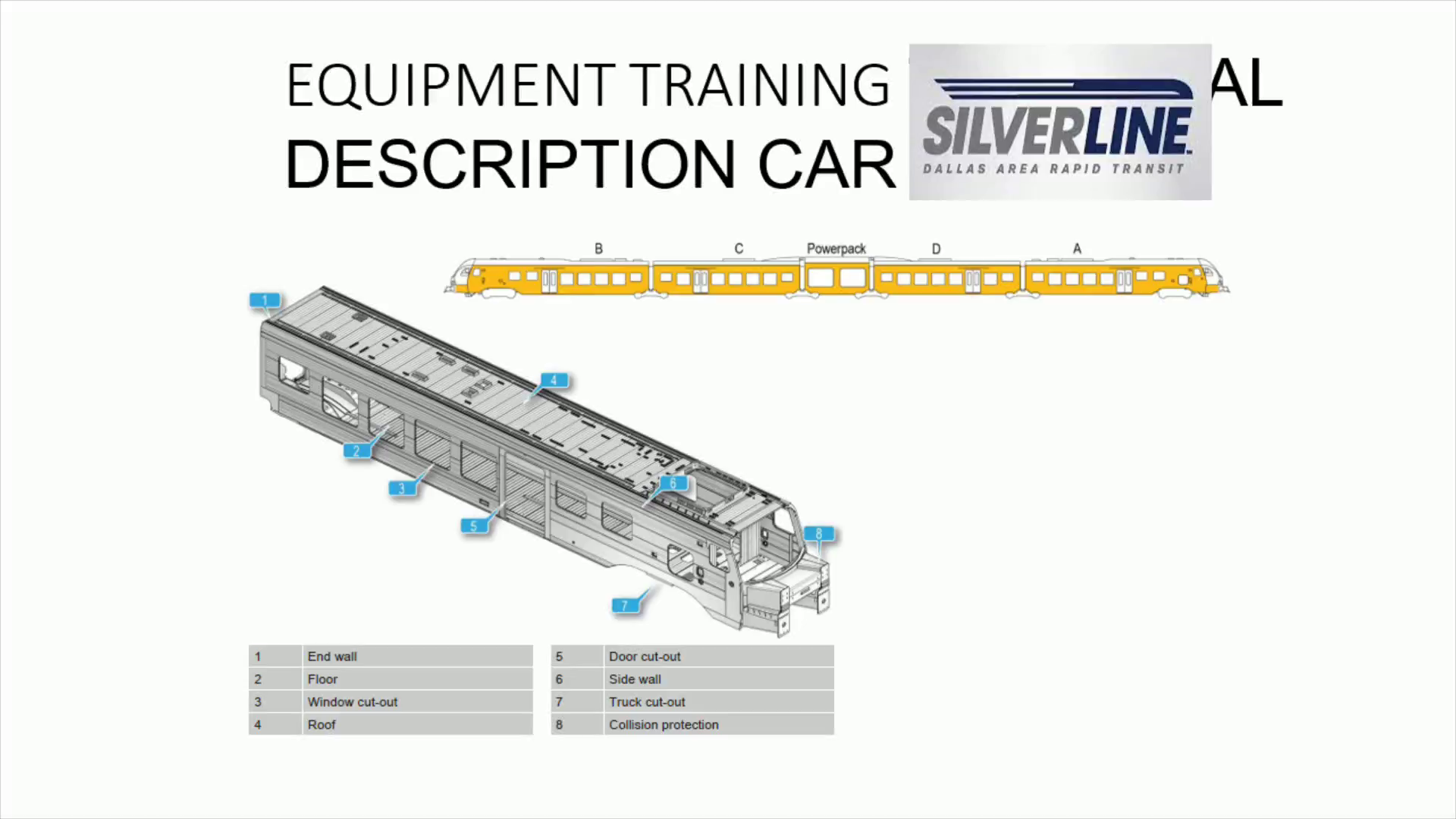
[Audio] Shown here is the car body of the flirt 3. The different components of the car body are labeled in the diagram such as number 5, the door cut out, and number 8 the collision protection..
Scene 2 (13s)
[Audio] In this diagram the collision protection of the vehicle is highlighted. The collision protection is tested in multiple scenarios including; head impact of similar vehicles at a speed of 22 miles per hour impact on a freight car of 80 metric tons at a speed of 22 miles per hour impact on a large truck at a grade crossing at a speed of 68 miles per hour and impact on a smaller object like a car at a grade crossing. For each scenario and train class there are minimum requirements on the remaining space in the driver cabin after the crash. The collision protection is integrated in the head of vehicle and absorbs the collision energy through controlled deformation. In the event of a collision, the driver's cab and its equipment are protected in the best possible way. In the event of a collision, the front coupler first absorbs a part of the collision energy by means of the towing equipment and buffing gear. If the force increases further, the shear bolts break and the front coupler, together with the coupler plate, is forced into a cavity provided for it under the operator's cab. The coupler can continue to absorb energy via a deformation pipe after the shear bolts have broken. The crash energy absorption modules also absorb energy. They are designed to deliberately deform. In addition, the jagged front of the crash absorption modules prevents the colliding vehicles from riding up over one other. If the crash energy absorption modules are no longer sufficient to absorb the collision energy, the crash energy absorption boxes absorb further energy. The crash energy absorption wall stays as a rigid structure and can thus protect the operator..
Scene 3 (2m 7s)
[Audio] Shown in this diagram are the multiple running gear of the vehicle, highlighted in yellow. Notice, there are only two sets of motor trucks. Truck number 1 and truck number 6..
Scene 4 (2m 22s)
[Audio] This is the diagram of a motor truck. The motor truck has the functions that follow: To transmit the motor power of the vehicle to the track. To guide the vehicle in the track. To brake the vehicle. To absorb various forces between the track and the vehicle. To carry the car bodies. and To guarantee smooth running of the vehicle..
Scene 5 (2m 51s)
[Audio] Each motor truck is equipped with a drive unit to supply power to the wheels..
Scene 6 (2m 59s)
[Audio] Shown here is a trailer truck, or Jacobs truck. The Jacobs truck has the functions that follow: To carry the car bodies. To guarantee smooth running of the vehicle. Technical description. To guide the vehicle in the track. To brake the vehicle. and To absorb various forces between the track and the vehicle..
Scene 7 (3m 28s)
[Audio] Highlighted in yellow on this diagram is the air suspension on the trucks..
Scene 8 (3m 35s)
[Audio] The air suspension also serves to level the car body around curves in the track and at platforms..
Scene 9 (3m 44s)
[Audio] The sanding system is activated manually by the driver. The sanding system is switched on automatically during emergency braking initiated by the driver or by passenger alarm equipment. The sanding system is switched off when the vehicle comes to a standstill or whenever the master controller is no longer in position for emergency braking initiated by the driver. The sanding system is located on the motor trucks of both end cars only. It cannot be found on the trailer trucks..
Scene 10 (4m 17s)
[Audio] The wheel flange lubrication is controlled by the vehicle control unit. This system allows the vehicle to automatically lubricate the wheel which in turn reduces wear on wheel and the rail. The spraying intervals change depending on the speed of the unit..
Scene 11 (4m 35s)
[Audio] Pictured here is the vehicle's Power Pack which consists of: four diesel generators, or motors, cooling systems, air intakes, pneumatic panels, electric cabinets, A fuel tank, exhaust systems, and fire extinguishing systems..
Scene 12 (4m 52s)
[Audio] The emergency stop buttons for the powerpack are shown here. There are some located on the exterior of the powerpack and on the interior..
Scene 13 (5m 3s)
[Audio] Power converter: Converts the generator current into traction current for the traction motors. Provides energy for electrical auxiliary equipment. And, Charges the main batteries / starter batteries..
Scene 14 (5m 21s)
[Audio] Fire protection: If the fire protection system detects smoke or overtemperature, the corresponding indicator lamps and pushbuttons then light up, notifying the operator of the fire alarm. The diagnostic display indicates the location of the fire alarm. The Power Pack and the battery compartment are monitored by the temperature sensors..
Scene 15 (5m 45s)
[Audio] Emergency intercom: If an emergency intercom is used, the operator receives a message on the passenger information system control unit. The microphone of the passenger information system allows the operator to speak to an emergency intercom. If there are multiple alarms, it is possible for the driver to talk to multiple emergency intercom systems one after the other..
Scene 16 (6m 12s)
[Audio] The S O S button the operators cab will illuminate when an emergency intercom alarm is triggered. To accept the and terminate calls from the passengers compartments the engineer would push the S O S button. The P T T button is held down to talk when the intercom is active..
Scene 17 (6m 32s)
[Audio] External lighting: The vehicle is equipped with modern, energy-efficient lights. This powerful lighting enhances safety through better vision and visibility. The headlights and marker lamps can only be operated from the active driver's cab..
Scene 18 (6m 50s)
[Audio] External doors: The vehicle has two external doors on every car and side..
Scene 19 (6m 58s)
[Audio] The door vestibule is equipped with buzzers and lights to inform customer when a does is opening or closing. There are also features available to disable a door in the event of a malfunction. Emergency door releases and intercoms can also be found in the vestibules..