Shear-Based Grasp Control for Multifingered Underactuated Tactile Robotic Hands
Scene 1 (0s)
IEEE TRANSACTIONS ON ROBOTICS, VOL. 41, 2025 3113 Shear-Based Grasp Control for Multifingered Underactuated Tactile Robotic Hands Christopher J. Ford , Haoran Li , Member, IEEE, Manuel G. Catalano , Matteo Bianchi , Member, IEEE, Efi Psomopoulou , Member, IEEE, and Nathan F. Lepora Abstract—This article presents a shear-based control scheme for grasping and manipulating delicate objects with a Pisa/IIT anthropomorphic SoftHand equipped with soft biomimetic tactile sensors on all five fingertips. These “microTac” tactile sensors are miniature versions of the TacTip vision-based tactile sensor, and can extract precise contact geometry and force information at each fingertip for use as feedback into a controller to modulate the grasp while a held object is manipulated. Using a parallel processing pipeline, we asynchronously capture tactile images and predict con- tact pose and force from multiple tactile sensors. Consistent pose and force models across all sensors are developed using supervised deep learning with transfer learning techniques. We then develop a grasp control framework that uses contact force feedback from all fingertip sensors simultaneously, allowing the hand to safely handle delicate objects even under external disturbances. This control framework is applied to several grasp-manipulation experiments: First, retaining a flexible cup in a grasp without crushing it under changes in object weight; Second, a pouring task where the center of mass of the cup changes dynamically; and third, a tactile-driven leader-follower task where a human guides a held object. These manipulation tasks demonstrate more human-like dexterity with underactuated robotic hands by using fast reflexive control from tactile sensing. Index Terms—Manipulators, robot control, tactile sensors. I. INTRODUCTION I N ROBOTIC manipulation, accurate force sensing is key to executing efficient, reliable grasping and manipulation Received 15 September 2024; revised 7 February 2025; accepted 20 February 2025. Date of publication 21 April 2025; date of current version 12 May 2025. The work of Christopher J. Ford, Efi Psomopoulou, and Nathan F. Lepora was supported by the Horizon Europe Research and Innovation Program under Grant 101120823 (MANiBOT). The work of Efi Psomopoulou and Nathan F. Lepora was also supported in part by the Royal Society International Collaboration Awards (South Korea). The work of Nathan F. Lepora was also supported in part by an award from ARIA on “Democratizing Hardware And Control For Robot Dexterity.” This article was recommended for publication by Associate Editor and Editor M. Yim upon evaluation of the reviewers’ comments. (Efi Psomopoulou and Nathan F. Lepora contributed equally to this work.) (Corre- sponding author: Nathan F. Lepora.) Christopher J. Ford, Haoran Li, Efi Psomopoulou, and Nathan F. Lep- ora are with the Department of Engineering Mathematics and Bristol Robotics Laboratory, University of Bristol, BS8 1QU Bristol, U.K. (e-mail: [email protected]; [email protected]; efi.psomopoulou@bristol. ac.uk; [email protected]). Manuel G. Catalano is with the Department of Soft Robotics for Human Cooperation and Rehabilitation, Istituto Italiano di Tecnologia (IIT), 16163 Genova, Italy (e-mail: [email protected]). Matteo Bianchi is with the Department of Information Engineering and the Research Center “E. Piaggio,”, University of Pisa, 56126 Pisa, Italy (e-mail: [email protected]). Digital Object Identifier 10.1109/TRO.2025.3563046 without dropping or mishandling objects. This manipulation is particularly challenging when interacting with soft, delicate objects without damaging them, or under circumstances where the grasp is disturbed. For complex manipulation tasks, it is expected that multifingered dexterous manipulators with many degrees of freedom are needed [1]. This freedom comes at the cost of greater complexity in their control, which can be partially ameliorated with the use of underactuated robot hands that have high degrees of freedom yet require far more basic control relative to their fully actuated counterparts, albeit at the expense of some dexterity [2], [3]. Another aspect of force-sensitive manipulation, is to have detailed information on contact pose, normal force, and shear force at the point of contact, which can be provided by high-resolution tactile feedback [4]. The tactile feedback could also help compensate for the lower dexterity of underactuated manipulators, which is a viewpoint that will be explored in this article. An underappreciated component of robotic manipulation is shear sensing from the point of contact. A recent study using a similar tactile sensor as the present work, showed that com- plex interactions with objects such as continuous pushing or holding contact under translational/rotational motion are only possible with knowledge of the contact shear [5]. While the grasp force may be inferred from the motor currents in fully actuated hands [6], this only resolves normal force. Furthermore, accurate measurements are not possible in underactuated hands without accurate kinaesthetic sensing, as grasp force cannot be accurately measured due to decoupling between the point of contact and actuators [4]. Therefore, for soft underactuated robotic hands, suitable shear sensing at the point of contact is key to robotic manipulation. Yet not all modern tactile sensors integrated into robotic hands are appropriate for sensing shear, as many only detect normal force or have low resolution and/or sensitivity [7]. A biomimetic marker-based tactile sensor, the Bristol Robotics Laboratory (BRL) TacTip, has been found particularly effective for slip and shear detection both with a single fingertip [8] and with multiple fingertips of a robot hand [9]. The unique feature of the TacTip is its biomimetic morphology, with markers applied to the ends of pins rather than just the sensing surface of the skin, which is inspired by the subdermal papillae structures through which humans perceive touch [10], [11]. Having the markers cantilevered in this way amplifies contact deforma- tion, making the sensor highly sensitive to slippage and shear. Likewise, the TacTip can also use local shear information to 1941-0468 © 2025 IEEE. All rights reserved, including rights for text and data mining, and training of artificial intelligence and similar technologies. Personal use is permitted, but republication/redistribution requires IEEE permission. See https://www.ieee.org/publications/rights/index.html for more information. Authorized licensed use limited to: NATIONAL INSTITUTE OF TECHNOLOGY ROURKELA. Downloaded on March 10,2026 at 06:19:46 UTC from IEEE Xplore. Restrictions apply..
Scene 2 (1m 5s)
3114 IEEE TRANSACTIONS ON ROBOTICS, VOL. 41, 2025 detect incipient slip, facilitated by a fingerprint-like structure [9], [12], although this remains a problem under investigation [13]. At the time of writing, whilst there has been progress in sensing shear force with tactile sensors, there has been no implementation of shear-based grasp control on a multifingered hand using feedback from multiple high-resolution tactile sen- sors. The benefit of this is that the sensors provide access to more information-rich contact data, which allows for more complex manipulation. The challenge comes from handling large amounts of high-resolution data, so that the processing does not slow down the system due to high computational demands. In the present work, we propose a novel grasp control policy for underactuated hands where a state of “pre-slip” is maintained by balancing normal and shear contact forces, which we apply to the single-actuated anthropomorphic Pisa/IIT SoftHand [14]. Forthiscontrol,weaccuratelypredict3-Dcontactposeandforce at the point of contact from five tactile sensors mounted at the fingertips of the SoftHand using supervised deep learning tech- niques. The tactile sensors used are miniaturized TacTip optical tactile sensors (called “microTacs”) developed for integration into the fingertips of this hand. This controller is applied to this underactuated grasp modulation during disturbances and ma- nipulation. We perform several grasp-manipulation experiments to demonstrate the hand’s extended capabilities for handling unknownobjectswithastablegraspfirmenoughtoretainobjects under varied conditions, yet not exerting too much force as to damage them. Our main contributions are as follows. 1) Control Methods for Handling Objects With an Underac- tuated Tactile Robotic Hand: We present a novel grasp con- troller framework for an underactuated soft robot hand that allows it to stably grasp an object without applying excessive force, even in the presence of changing object mass and/or external disturbances. The controller uses marker-based high resolution tactile feedback sampled in parallel from the point of contact to resolve the contact poses and forces, allowing use of shear force measurements to perform force-sensitive grasping and manipulation tasks. 2) Hardware Advancements Consisting of a Complete Tactile Hand-Arm Robotics System With Custom Tactile Fingertips and Computational Processing Architecture: We designed and fab- ricated custom soft biomimetic optical tactile sensors called mi- croTacs to integrate with the fingertips of the Pisa/IIT SoftHand. For rapid data capture and processing, we developed a novel computational hardware platform allowing for fast multi-input parallel image processing. 3) SoftwareMethodsforMultitactileSensorLearningofPose and Shear: A key aspect of achieving the desired tactile robotic control was the accurate prediction of shear and normal force and pose against the local surface of the object, for each tactile fingertip. This was achieved using supervised deep learning methods extended to five tactile sensors concurrently (from one in previous work [15]). We find a combination of transfer learning and individual training gave the best models overall, as it allows for learned features from one sensor to be applied to the others. II. BACKGROUND AND RELATED WORK A. Force-Sensitive Grasping The elasticity of underactuated hands is beneficial for grasp- ing performance, but introduces issues when considering force- sensitive manipulation. Historically, such applications employ some method to transduce the forces being experienced at each finger joint in order to resolve grasping force [16], [17], [18], [19], [20]. This method is straightforward when using rigid finger joints due to their predictable kinematics, but does not work well with soft underactuated hands and/or soft contacts due to the nonlinearities introduced to the system from elasticity [21]. This is due to the elasticity in the kinematic chain absorbing an unknown amount of force from that generated by the the payload mass, causing inaccuracies in inferring contact forces. This makes it difficult to apply other established methods for force sensing, which require an analytical model of the system [22], [23]. It is well documented that measurements taken di- rectly from the point of contact are essential when considering advanced robotic manipulation tasks, such as in-hand manipu- lation [16], [24], [25]. Ajoudani et al. [26] proposed a system where a Pisa/IIT SoftHand [14] with tactile fingertips reacts to changes in grasped object mass or external disturbances on grasped objects, adjusting accordingly to retain the object. The fingertip sensors used were ThimbleSense sensors [27] that are approximately the size of human fingertip, using an ATI Nano 17 Force/Torque sensor that could resolve 6-axis forces to a high degree of precision at a high frequency (0.003 N resolution for translational force at 7 kHz [28], [29]). However, they have limited sensory information compared with array-based or optical tactile sensors. For this reason, we focus here on using high-resolution soft optical tactile sensors. B. Tactile Control Li et al. [30] and Kappassov et al. [31] presented control frameworks for tactile servoing based on calculating geometric contact features suitable for guiding the sensor. Both studies use sensors with flat taxel arrays to infer contact features such as area of contact and the contact moments, which is then used as feedback into a servo-controller for the robot to execute contact tracking and contour-following tasks. These features are calculated analytically from the taxel array values, and are only suitable for control of rigid tactile arrays of known shape (e.g., flat in these two studies). Work on tactile servo control with soft curved optical tactile sensors has instead used the surface contact pose as feedback to move a robot arm with tactile end effector [32]. The components of the surface contact pose are found by training a convolutional neural network (CNN) to predict the contact pose through su- pervised deep learning over a dataset of tactile images of known poses [33]. In the original work, shear was treated as a “nuisance variable” and the training data collection introduced random unlabeled shear perturbations, which enabled the learnt model to be insensitive to unknown motion-dependent shear. Later work has extended the model to also predict shear displacement [5], but required use of technically-sophisticated methods involving Authorized licensed use limited to: NATIONAL INSTITUTE OF TECHNOLOGY ROURKELA. Downloaded on March 10,2026 at 06:19:46 UTC from IEEE Xplore. Restrictions apply..
Scene 3 (2m 10s)
FORD et al.: SHEAR-BASED GRASP CONTROL FOR MULTIFINGERED UNDERACTUATED TACTILE ROBOTIC HANDS 3115 a Bayesian filter and Gaussian density network to reduce pre- diction uncertainties, for example from slippage during training data collection. Shear cannot be ignored when handling an object against the force of gravity, as it provides key information on how to secure the held object [34]. Meanwhile, tactile servo control without shear has been successfully applied to many single- sensor tasks, such as contour following [35], surface following [32], or pushing tasks [36]; however, these tasks only require measurements of contact depth and orientation to achieve. Lloyd and Lepora [5] introduced pose and shear-based tactile servoing able to predict shear displacement as described above, however, the Bayesian filtering required an estimate of the changes in tactile sensor pose, given by the robot arm kinematics on which the sensor was mounted. Thus, their approach cannot be applied to underactuated robot hands without knowledge of the finger joint positions. In the present work, we use a force/torque (FT) sensor to sample the resultant normal and shear contact force as part of the data collection protocol and so train a model to predict force. As stated, previous work in predicting 6-degree of freedom (DoF) pose with the TacTip shows that shear displacement is difficult to predict accurately due to the sensor slipping during data collection [5]. This introduces discrepancies between the pose label and the resulting tactile image, which manifests as noise in the data. However, by sampling the resulting shear force from a given shear displacement we generate the label after any slip event has occurred. This effectively filters out noise in the data due to slip, enabling accurate shear-force predictions. C. Robot Hands Robots intended for manipulation tasks should provide dex- terity while minimizing the complexity of their control, which requires a balance between the degrees of freedom and degrees of actuation (DoAs), which is a quantity that defines the number of motors in the hand. For example, a fully-actuated hand with many DoFs such as the Shadow dexterous hand is very dexterous, but can be complex to control [37]. Reducing the DoAs to simplify control is one solution, but does sacrifice some dexterity [38], [39], [40]. One way to compensate for this loss of dexterity is to use compliance in the robot hand [41], allowing the hand to passively conform to the shape of held objects [42]. Here,weusethePisa/IITSoftHand:ananthropomorphichand that modulates the grasp in a whole hand pinch grasp, based on a motion derived from human postural synergies [14] [43]. This hand is highly underactuated, with only 1 DoA, yet 19 DoF. It would be difficult to achieve good grasping performance with such limited actuation; however, the SoftHand mitigates this loss of dexterity (albeit at the loss of joint proprioception and, therefore, understanding of the exact grasp pose) by adding compliance into the mechanism via “dislocatable” joints in the fingers, realized as rigid phalanxes coupled via elastic linkages with a tendon-drive mechanism [43]. Together with the human- like postural synergy of grasp closure this forms an “adaptive synergy” where grasping performance is improved despite a lack of dexterity from underactuation [14]. TABLE I PROPOSED MICROTAC IMPROVED RESOLUTION COMPARED TO THE STANDARD TACTIP FROM REFS [8], [10], [32], AND DIGITAC [46] III. HARDWARE METHODOLOGY A. Microtac Soft Biomimetic Optical Tactile Sensor 1) Maximizing Marker Density: As we will require accurate shear information on human-fingertip sized sensors, we consid- ered it important to maximize the number of pins and markers (the papillae-like structures on the interior of the skin and the spots of contrasting color to the skin, located on the tips of the pins, respectively). Markers are the primary features for predictingshear,sohighermarkerdensityshouldimprovesensor prediction accuracy [11], [44]. It should be noted that although images are downsampled, marker density and downsampling are independent factors in- fluencing performance. Downsampling trades off some benefits of high-marker density but would have more impact on sensors with low-marker density [45]. Improving the marker resolution is particularly important when considering a smaller sensor due to the inherently smaller visible contact area. However, this proves challenging for a TacTip, as smaller pins and markers can break more easily duringmanufacture.Toaddressthisissue,wedevelopedadesign approach to parameterically alter the number of pins as well as their diameter and height. This resulted in an efficient iterative workflow through which we were able to quickly determine the highest marker resolution able to be manufactured, to create a new sensor designed specifically as a fingertip for the Pisa/IIT SoftHand that we call the microTac (design shown in Fig. 1; comparison with TacTip shown in Table I). This design study resulted in a sensor with 217 pins (from 127 pins on a larger TacTip) despite reducing the diameter of the sensor by 50% from 4.2 cm to 2.1 cm. In terms of marker density, this translates to approximately 31 markers/cm2 as opposed to 4 markers/cm2 on a full-sized TacTip, giving an increase of marker resolution by 775%. Table I also shows a comparison with another sensor devel- oped in BRL, the DigiTac [46], which is relevant as it has also been integrated into the fingertips of robot hands [47], [48]. It is a version of the Meta DIGIT [49] modified to sense tactile information through the TacTip pins-and-markers mechanism. Table I shows the microTac is smaller than the DigiTac, yet has a pin density almost 50% larger. As far as we are aware, this design represents the highest marker density on this type of optical tactile sensor at the time of writing. Other works describe high-density marker arrays [50]; however, those tactile sensors feature 2-D marker patterns printed on the skin or embedded in the elastomer. As discussed in the introduction, the markers on the TacTip skin are can- tilevered on the end of pins in an artificial papillae structure, which increases the sensitivity by amplifying deformation of Authorized licensed use limited to: NATIONAL INSTITUTE OF TECHNOLOGY ROURKELA. Downloaded on March 10,2026 at 06:19:46 UTC from IEEE Xplore. Restrictions apply..
Scene 4 (3m 15s)
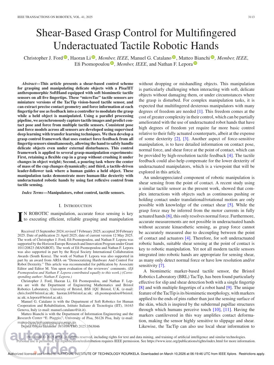
3116 IEEE TRANSACTIONS ON ROBOTICS, VOL. 41, 2025 Fig. 1. Proportional, integral and derivative (CAD) model of the microTac soft biomimetic optical tactile sensor. (Top) The microTac dome compared to a standard TacTip dome. (Bottom) Side and cross-sectional views of the microTac, showing the internal camera viewing the marker-pin array protruding into the fingerprint bumps. Overall, the microTac is approximately the same size as the pad of a human fingertip. the skin into shear displacement of the markers. This TacTip design requires a morphologically-complex skin structure that is enabled by modern 3-D-printing techniques, but nevertheless makes it more challenging to optimize aspects such as marker density. The sensor is printed as a single part on a Stratasys J826 Prime multimaterial 3-D printer, with the tip body made of Vero Black, the skin of Agilus30 Black, and the markers of Vero White. After printing, a clear acrylic window is installed to form a sealed cavity beneath the skin, into which TECHSiL RTV27905 clear silicone encapsulant is injected. 2) Artificial Fingerprint: The microTac features an artificial fingerprint, based on a patterns of bumps that have previously been shown to improve the spatial acuity of TacTip-style sensors [51]. Here, this outer skin structure was primarily used to extend the effective pin length, as the height of the pins was reduced to accommodate the higher marker density. The fingerprint structure(seecross-sectioninFig.1)iscomprisedofmanyraised sections of outer skin material, each of which is concentric with a pin on the interior skin. B. Robotic Tactile Hand-Arm and Computing System The experimental robot system we use in this work (see Fig. 2) is comprised of two actuating robots: a Universal Robots UR5 6- DoFindustrial robot arm and a 1-DoAPisa/IITanthropomorphic Fig. 2. Robot hardware and computing infrastructure. (a) microTac tactile fingertips mounted on the Pisa/IIT SoftHand, which is mounted on the wrist of a UR5 robot arm. The arm-hand system is shown oriented in the neutral pose in which the palm faces horizontally with the thumb up. Also shown is the sensor frame, illustrating how pose and force variables are oriented relative to the sensing surface. (b) System architecture of the sensing and computing components of the robotic system, comprising tactile sensor inputs to a Jetson Nano array, coupled by a router to a control PC, which controls the UR5 robot arm and Pisa/IIT SoftHand. The Jetson Nano array allows on-board tactile image capture, processing, and model prediction, to minimize the computational load on the control PC. (c) Visualization of the image processing pipeline, illustrating how skin deformation from sensor contact is imaged, processed, and converted to pose and force values. (a) Robot arm-hand system. (b) Computing infrastructure for tactile processing and control. (c) Image processing pipeline. SoftHand, as well as a tactile sensing component comprising the five microTac tactile sensors. The tactile sensors are mounted as fingertips on the SoftHand, which is in turn mounted as an end- effectorontheUR5robotarm.Eachsystemelementisconnected toacentralcontrolPC(DellPrecisionwith16GBRAMandIntel Core i7-13700), to process the tactile information and control the robot and hand. Communication with the actuating elements Authorized licensed use limited to: NATIONAL INSTITUTE OF TECHNOLOGY ROURKELA. Downloaded on March 10,2026 at 06:19:46 UTC from IEEE Xplore. Restrictions apply..
Scene 5 (4m 20s)
FORD et al.: SHEAR-BASED GRASP CONTROL FOR MULTIFINGERED UNDERACTUATED TACTILE ROBOTIC HANDS 3117 is via their proprietary software APIs in a way that allows for asynchronous control of the robot arm and SoftHand. A new challenge was posed by capturing five USB camera- based tactile sensor inputs simultaneously at minimal latency and a reasonable frame rate, as most standard PCs do not have sufficient processing buses. Therefore, we developed a novel processing architecture that can capture and process tactile images from each sensor in parallel. This consists of five Nvidia Jetson Nano ARM64 microcomputers (one for each sensor), which capture tactile images at 1280×720 p, then process and downsample the images to 240×135 p (using bilinear interpola- tion) before passing through a neural network model processing pipeline illustrated in Fig 2(c). These low-cost Jetson boards each has a solid-state GPU with 128 CUDA cores, which makes them capable in deploying embedded AI applications (as opposed to other microcomputers, such as a Raspberry Pi). The Jetson array means that data from the sensors is captured and processed in parallel, which gives a significant benefit over managing separate processes or threads on the control PC, as the computational demands associated with capturing and process- ing high-resolution tactile images are distributed across multiple submodules. We found this parallel processing to be essential, since images need to be captured at high resolution with low latency to process the relevant tactile information for the robot control. Utilizing the Jetson array means we can capture images from all sensors in parallel at a high resolution, with subsequent image processing executed asynchronously on each board. This parallel image capture reduces latency that would be introduced by capturing images sequentially. Consequently, the sensing frequencyislimitedonlybythecameraframerate,allowingusto runourcontrolalgorithmwithanaveragesamplingrateof60Hz. Data from the sensors is accessed using the Pyro4 distributed computing library to instantiate virtual sensor objects on the local network, which gives a class of functions for capturing images, processing images, and running model inference. Using Pyro4, these functions can be accessed virtually from the control PC and used in a central Python control program as if the sensors were connected to the PC directly. This process reduces the size of the data packets coming to the control PC from the tactile sensors, so they can be managed in separate threads (along with communications to and from the UR5 arm and Pisa/IIT SoftHand), resulting in an asynchronous robotic system capable of real-time response and control. IV. SOFTWARE METHODOLOGY A. Contact Pose and Force Data Collection The tactile robot was used in a different configuration to collect data for training. A custom end effector mount was fabricated so a microTac tactile sensor could be mounted on the wrist of the UR5 robot arm. In addition, a force-sensitive surface was created comprising a flat surface mounted on an ATI Mini 40 FT sensor (which was chosen for its high accuracy, low noise, and low drift), which was itself mounted in a fixed position relative to the robot arm. TABLE II POSE AND SHEAR PARAMETER RANGES USED FOR TRAINING DATA COLLECTION, AND CORRESPONDING RANGES OF THE MEASURED FORCE The microTac was brought into contact with the force- sensitive surface at a variety of predetermined poses sam- pled randomly from uniform distributions within the ranges in Table II. The data collection is based on that used to “train accurate pose models for surfaces and edges” from [33], which formed the basis for prior work on tactile servo control with the TacTip [5], [32], [36]. The surface pose relative to the tactile sensor is set by the contact depth and orientations (z, α, β), and the contact shears (x, y) by an additional shearing motion while the sensor is in contact with the surface. These pose and shear parameters result in a normal and shear contact force (Fx, Fy, Fz) whose measured ranges are also shown in Table II. Rotational γ-shear and related torques were omitted as prelimi- nary testing indicated that torsional slippage occurred at around 1.3 Nmm corresponding to z-displacements at the upper end of the range shown in Table II. We also decided to only consider the translational (normal and shear) components of force to simplify the control and analysis. Due to the extreme underactuation of the SoftHand, grasp stability is controlled through monitoring thedistributionofforcesacrossthegrasp,asindividualfingertips cannot be controlled. Therefore, small changes in torsional shear make little difference in the situations considered in this article where the object’s center of mass lies inside the grasp enve- lope; furthermore, their inclusion would greatly complicate the control strategy. Other manipulation scenarios where torsional shear may be appreciable would require extension of the control strategy. For each tactile image sample, the sensor was brought into contact with the surface at the defined orientation and depth, then sheared across the surface to the defined shear displacement. The resulting tactile image was captured and the forces sampled from the FT sensor, with image and force capture processes running in parallel and synchronized by timestamp to ensure the correct data was extracted. Data captured from the FT sensor at each time step was taken as a moving average across 50 samples, then a Butterworth filter was used to further smooth the signal across the entire tap-and-shear movement for that point of data collection. This type of hybrid filtering approach is common when balancing local noise reduction and overall signal smoothing, and found to be important in this case due to a small signal-to-noise ratio. In these cases, the moving average filter smooths local high frequency noise first allowing the subsequent Butterworth filter to work more efficiently on the broader frequency components of the signal [52], [53]. Overall, 3000 tactile images were taken for each sensor and were split 80/20 to give 2400 training images and 600 validation Authorized licensed use limited to: NATIONAL INSTITUTE OF TECHNOLOGY ROURKELA. Downloaded on March 10,2026 at 06:19:46 UTC from IEEE Xplore. Restrictions apply..
Scene 6 (5m 25s)
3118 IEEE TRANSACTIONS ON ROBOTICS, VOL. 41, 2025 Fig. 3. Different approaches for supervised learning of tactile pose and force prediction models based on CNNs. (a) Individual models: Five single models are trained on data from each sensor individually. (b) Aggregate model: One model is trained on data aggregated from all five sensors. (c) Progressive transfer model: one model is trained progressively on data from each of the five sensors in turn. (d) Standard transfer models: Five individual sensor models are trained on data from each sensor individually, from a pretrained model trained on data from all five sensors. images per sensor. A separate test dataset of 600 images was also collected for each sensor. The test data is distinct from the validation data in that it is unseen by the model during training to provideanobjectiveperformanceevaluation.Thetestsetverifies that any apparent accuracy in the trained models will generalize to new, previously unseen data, ruling out overfitting. B. Contact Pose/Force Model for Multiple Sensors Initially, a model was trained using the data for each sensor with the CNN architecture from [33]. The training and model hyperparameters are given in Table V (see Appendix A) and are from previous work using a TacTip to estimate surface pose [33]. Each CNN takes a 240 × 135 px tactile image as input and outputs a 6-component vector of pose and force predictions, namely, [z, α, β, Fx, Fy, Fz] [as shown in Fig. 2(c)]. As force should increase monotonically with translations in the x-, y-, and z-directions, we expect that the model can use same tactile image features for force as for the pose counterpart from [33]. Details of the network structure and hardware are given in Appendix A. Since data from multiple sensors was available, we investi- gatedwhethertransferlearningcouldbeusedtoimproveindivid- ual model performance. Initial investigations showed that a force prediction model for one sensor cannot be directly used to make accurate predictions for another, which we attribute to small physical discrepancies between them resultant of manufacturing and assembly. However, as the marker layout is similar for all sensors, we expect that some trained features would be common to all sensors regardless. Thus, we expect that a model that has inherited the weights and biases of a pretrained model designed to work in the same feature space but from different sensors would be better at generalizing between sensors to improve overall accuracy and robustness. Four learning approaches were compared (summarized in Fig. 3). The baseline is an individual model approach; i.e., Fig. 4. Shear-based grasp controller architecture. The gentle grasp controller uses an SSIM measure of contact deformation to establish a stable yet gentle grasp on an object. Meanwhile a force-feedback controller uses force predictions from the tactile sensors to modulate the grasp in response to external distur- bances. These controllers feed into the hardware interface (plant) comprising the SoftHand microcontroller and tactile model prediction array that are depicted in more detail in Fig. 2. the same training method described above. Next, an aggregate approach was taken, which trains a model on a dataset from all sensors. Two typical transfer learning approaches were taken: First, progressive transfer learning, (which trains an individual modelsuccessivelywithdatafromallsensors,inheritingweights and biases from the previous iteration [54]); and, second, stan- dard transfer learning, which trains individual models from data foreachsensor,inheritingtheweightsandbiasesoftheaggregate model [55]. Once learned, instances of models may be sent to individual Jetson Nanos in the processing array and deployed in parallel. C. Control Framework The controllers used in this study all use force feedback from the tactile sensors to affect a system response, whether that is grasp adjustment or a change in robot arm velocity. In this section, we will first introduce our grasp controller framework used in Experiments 1 and 2, followed by the velocity controller used in Experiment 3. The grasp controller used in this study aims to gently grasp an object and retain it in response to external disturbances by modulating the grasp force. The general architecture is shown in Fig. 4 and has two main components described below. Gentle grasp controller : The objective of this controller is to establish and maintain a light contact, applying just enough force to retain it. This controller uses the average structural similarity index measurement (SSIM) [56], an established measure for contact detection in optical tactile sensors [4], [57] that functions by calculating a percentage similarity between two images. It is calculated as follows: SSIM (Img, Img0) = (2μxμy + c1) (2σxy + c2) (μ2x + μ2y + c1)(σ2x + σ2y + c2) (1) where x and y represent an n × n kernel of pixels applied as a sliding window over each image. σ and μ represent the mean and covariance of each kernel calculation, with c1 and c2 acting as regularizing constants to stabilize the division [57]. The SSIM is given as an averaged final value, SSIM ∈ [0, 1], where SSIM = 1 Authorized licensed use limited to: NATIONAL INSTITUTE OF TECHNOLOGY ROURKELA. Downloaded on March 10,2026 at 06:19:46 UTC from IEEE Xplore. Restrictions apply..
Scene 7 (6m 30s)
FORD et al.: SHEAR-BASED GRASP CONTROL FOR MULTIFINGERED UNDERACTUATED TACTILE ROBOTIC HANDS 3119 indicates the images are identical and SSIM = 0 indicates they have zero similarity [56]. In the gentle grasp controller, the SSIM of a baseline, un- deformed sensor image and the current sensor image is taken across all the sensors to establish and maintain a light contact using two sequential proportional controllers, each optimized for states where contact is and is not detected [4]. Force feedback controller : This controller uses force pre- dictions from the tactile sensors to modulate grasp force after an initial grasp is established by the gentle grasp controller. The change in shear forces, ΔFx and ΔFy, are used as feedback vari- ables, computed over one time step (17 ms average). By defining a controller setpoint of ΔFx = ΔFy = 0 N and using the error from the setpoint as feedback, we describe control behavior that will minimize the change in shear force by modulating the grasp force, retaining the object in the grasp. This is achieved by a standard proportional, integral and derivative (PID) controller. The tuning criteria for the gains of the force-feedback controller were to give a response, which was sensitive to both fast and slow disturbances and would not drop nor damage the held object. Due to the highly underactuated nature of the SoftHand and the nonlinearity of the dislocatable finger joints, the system cannot be easily assessed using traditional control engineering methods such as frequency response. Consequently, the system was manually tuned to a point where the observed behavior met the quantitative criteria outlined in Section V-A. The underactuation and soft nature of the SoftHand also means the exact pose of the sensors relative to the global frame cannot be known. Therefore, we define a “grasp frame,” defined as the average of all contact shear forces from all sensors, taking the form of a pair of resultant shear force vectors, Fx and Fy, which align with the xG- and zG-axes of the global frame (as shown in Fig. 5) when the robot arm is in starting pose with the thumb facing upward and the palm surface parallel with the global xz-plane [see Fig. 2(a)]. 1) Static Robot With External Disturbance: The grasp frame has the same orientation with respect to the global frame as the wrist frame of the UR5 robot arm. Thus, the pose of the grasp frame relative to the global frame may be resolved as a translation from the wrist frame pose, which is known from the kinematics of the robot arm. To define the grasp frame, we use the sum of the shear forces across all fingers inboththex- andy-directions. Therateof shear forceateachtimestep,ΔFx andΔFy,isfoundbycalculatingthe backward finite difference of the shear force in each direction. Thisistakenacrossanintervalof50samplestoreducecorrelated noise in the signal. 2) Nonstatic Robot With External Disturbance: When the robot arm is in motion, the dominant shear force direction will change with the orientation of the grasp relative to gravity. This presents several unique challenges compared to the previous static case, with the aim being to continually maintain a stable yet gentle grasp regardless of the orientation with respect to gravity or the variability of an object’s mass. Unlike the static case, the shear forces in the x-direction must be considered along with those in the y-direction, as the Fx vector no longer remains perpendicular to gravity at all times. Fig. 5. Various frames of reference and force components used for controlling the Pisa/IIT SoftHand on the robot arm. The global frame is the base frame of the UR5 robot arm, with the hand in the wrist frame of that robot. The force predictions from the individual tactile sensors are in the frames of those sensors (shown here as frames at each fingertip, where the superscript indices P, R, M, I, and T refer to the Pinky, Ring, Middle, Index, and Thumb digits, respectively), which are consolidated into a single force vector by averaging the shear forces at each fingertip. The x- and y-axes for the force vector are assumed to align with the xw- and yw-axes of the wrist frame, allowing the orientation of the shear force vector to be resolved from the robot kinematics. This complexity is handled by adding an additional controller with the same PID structure that was applied to the y-shear in the static case with different gains to control shear in the x-direction. Itwasfoundtobenecessarytohaveseparatecontrollershandling the x- and y-shear (as opposed to one controller considering the overall tilting angle) as the grasping behavior is highly dependent on the dominant shear axis. An aggregate controller was initially trialled, however, was found to be more difficult to tune to the desired behavior than two independent controllers. Because the Pisa/IIT SoftHand is underactuated, a change in grasp position tends to induce a small shear force in the nondominant shear direction due to the fingertips moving on the contact surface. Hence, using the same control architecture as describedabovecancausethehandtograspwithexcessiveforce, because it will interpret this additional shear force as a result of the grasp disturbance rather than a side-effect of grasp force modulation. To address this problem, we scale each shear force vector according to its orientation relative to gravity, which is crucial as it is necessary to know when the hand is upside-down. Therefore, we use the following as inputs to each controller: ux = SxΔFx, uy = SyΔFy (2) where Sx and Sy are scaling factors Sx = 1 − 2θx π , Sy = 1 − 2θy π (3) and θx and θy are the angles between gravity and Fx and Fy, respectively, (see derivation in Appendix B). Authorized licensed use limited to: NATIONAL INSTITUTE OF TECHNOLOGY ROURKELA. Downloaded on March 10,2026 at 06:19:46 UTC from IEEE Xplore. Restrictions apply..
Scene 8 (7m 35s)
3120 IEEE TRANSACTIONS ON ROBOTICS, VOL. 41, 2025 To find θx and θy given a static XYZ (SXYZ) Euler rotation (α, β, γ) (taken as the pose of the grasp frame relative to the robot’s base frame), we first find the product of the rotation matrices for each axis as follows: RSXYZ = Rz(γ) Ry(β) Rx(α). (4) We can then find the rotated x- and y-axes x′ = RSXYZ · � 1 0 0 �T , y′ = RSXYZ · � 0 −1 0 �T . If the gravity vector, g = � 0 0 −1 �T , is in the −zG direction of the global frame (as shown in Fig. 2), then θx and θy can be found using θx = arccos � g · x′ ∥g∥ ∥x′∥ � , θy = arccos � g · y′ ∥g∥ ∥y′∥ � . (5) 3) Control of Robot Under Externally-Applied Forces: As discussed in Section II, more traditional methods of robotic control through force sensing (such as a FT sensor in the wrist of the robot) do not apply well to the SoftHand due to the elasticity of the finger joints. By using tactile feedback, we are able to translate disturbances to the grasp into a velocity control signal for the robot, instructing it to move with the applied force. Assuming the SoftHand is grasping an object, an external force can then be applied to the object. The resultant magnitude and direction of this applied force relative to the global frame can be resolved and translated into a velocity control signal for the UR5 robot arm, whereby it will move in the direction of the applied force at a velocity proportional to the magnitude of the applied force. Here, we consider transforming the 3-D force vector (Fx, Fy, Fz) into a linear velocity vector ( ˙x, ˙y, ˙z). Only linear velocities are considered, as only linear forces, not torques, are used in the prediction process, constraining the robot to only translational movements. The components of the velocity vector align with the xw-, yw-, and zw-axes of the wrist frame of the robot (see Fig. 5). As previously mentioned, the fingertip positionsandorientationswithrespecttotheglobalframecannot be known due to the lack of proprioception in the finger joints; thus, the force components Fx and Fy are taken as the sum from each fingertip. The force component Fz is defined as the sum of the normal force experienced by all fingers and is assumed to act perpendicularly to Fx and Fy (see Fig. 5). The velocity control of the robot arm is then given by a system of linear equations that produces a linear velocity vector acting in the resultant direction of the applied forces as follows: ⎡ ⎢⎣ ˙x ˙y ˙z ⎤ ⎥⎦ = ⎡ ⎢⎣ kx(Fx) 0 0 0 ky(Fy) 0 0 0 kz(Fz) ⎤ ⎥⎦ ⎡ ⎢⎣ Fx Fy Fz ⎤ ⎥⎦ (6) where the controller input is the predicted force vector (Fx, Fy, Fz) at the current time-step. The velocity control is handled by the proprietary controller on the UR5 robot arm. To scale the output proportionally to the magnitude of the ap- plied force, the ratio of the applied force relative to its maximum value (see Table II) is multiplied by a base proportional gain Algorithm 1: Static Grasp Stabilization. 1: establishGrasp() 15: i = 0 16: while True do 17: Fy ← extractShear(predictions) 18: if i ≥ δ then 19: ΔFy ← Fy[i] − Fy[i − δ] 20: softhand.setPosition(pidController(ΔFy)) 21: else 22: doNothing() 23: end if 24: i + + 25: end while k0 to create a dynamic proportional gain k(F) = k0|F|/Fmax, where Fx,max = Fy,max = 20 and Fz,max = 60. The effect of this is that smaller signal perturbations, such as that from sensor noise, are diminished to prevent unwanted movement. (Note that (6) results in an F|F| term in the controller, which as described above results in a force-modulated gain acting on a force.) Then, the base proportional gains kx,0, ky,0, and kz,0 were tuned such that a user input magnitude greater than ±0.2 N would initiate robot movement, so as to eliminate sudden movements at low input forces. This procedure results in a controller tuned to tasks with these force ranges. For each controller presented in this section, once the control parameters were tuned it was found that the desired controller behavior generalized to objects of differing geometry and stiff- ness. This is to be expected given results from previous work on grasp controller development with this sensorimotor platform [4]. V. EXPERIMENTAL METHODOLOGY A. Experiment 1: Static Robot With External Disturbance For the first experiment, we mount the tactile SoftHand on a UR5 robot arm, and seek to maintain a grasp whilst grasping a cup as rice is added to the cup to disturb that grasp. A deformable paper cup is used to exhibit how the system is able to grasp an object with just enough force to maintain stability without crushing, which can only be reliably achieved with such a hand via tactile sensing and control [4]. Initial testing found that the paper cups used in our experiments permanently deformed (i.e., Authorized licensed use limited to: NATIONAL INSTITUTE OF TECHNOLOGY ROURKELA. Downloaded on March 10,2026 at 06:19:46 UTC from IEEE Xplore. Restrictions apply..
Scene 9 (8m 40s)
FORD et al.: SHEAR-BASED GRASP CONTROL FOR MULTIFINGERED UNDERACTUATED TACTILE ROBOTIC HANDS 3121 were crushed) under Fz loads of approximately 9 N. In addition, under initial gentle grasp conditions the cup began to slip after approximately 20 g of rice had been added. We use the controller that retains a static grasp under an external disturbance (Section IV-C1). For this experiment, the change in shear force ΔFx is assumed to be 0 as the hand is grasping the cup whilst keeping a vertical orientation; therefore, the x-component of the force (as seen in Fig. 5) is perpendicular to gravity and has no effect on the system. In the procedure for this experiment (see Algorithm 1), the hand first closes onto the cup and maintains a stable, gentle grasp, then the control switches to the force feedback controller. At this point, rice is added to the cup to destabilize the grasp. Three different masses of rice were used (100 g, 200 g, 300 g) to test that the controller responds as intended to a range of disturbance conditions. An initial test with an empty cup and constantgraspingforceofFz ≈ 2Nwasconductedasabaseline, which failed the task by deforming the cup. Higher grasp forces in the task are only possible when there is mass in the cup due to the outward pressure exerted, which is why a dynamic control strategy is necessary. Evidence of this is shown in the Supplementary Material. To ensure that the controller gives a desirable response to both fast and slow disturbances, step and ramp input tests were performed. The tuning criteria for these tests are as follows: Step input : The error signal (ΔFy) should settle to a setpoint (0±0.05 N/s) within 0.5 s for the maximum input (300 g rice). The plant response (SoftHand’s motor position) will exhibit some oscillation due to elasticity in the system; however, the grasp force (Fz) should not exceed the cup’s crush force (9 N). Ramp input : The error signal should not exceed 0.25 N/s. The plant response should increase steadily throughout the test with a steeper gradient for higher masses of rice. The grasp force should track the plant response, yet not exceed the crush force. For both cases, the cup may slip in the grasp, but must not be dropped. The tuned gains are given in Table VI, Appendix C. B. Experiment 2: Moving Robot With External Disturbance For the second experiment, we examined the situation where the orientation of the hand is not static while the grasp is destabilized. The rice is poured into the cup like in Experiment 1, then the arm is rotated about the grasp frame such that the rice is poured out of the cup. During this movement, the center of mass of the cup will shift due to the fluid motion of the rice, before the mass of the entire object (rice plus cup) changes as the rice is poured from the cup. We use the controller for a nonstatic robot with external disturbance (see Section IV-C2) with gains described in Table VI, Appendix C. In the procedure for this experiment (see Algorithm 2), the robot is rotated about the grasp frame (see Fig. 5) by an angle that is sufficient to pour the rice out of the cup. There are a family of possible rotations (α, β, γ) that could be applied to the hand. However, a pure γ rotation around the z-axis is actually the most challenging, as the friction of the grasp is opposing the entire mass of the cup for the whole motion; i.e., there is no point where the mass is partially or fully supported by either the Algorithm 2: Dynamic Grasp Stabilization. 1: establishGrasp() 2: i = 0 3: while True do 4: pose ← robot.getPose() 5: α, β, γ ← extractRotation(pose) 6: θx, θy ← eulerRotation(α, β, γ) 7: Fx, Fy ← extractShear(predictions) 8: if i ≥ δ then 9: ΔFx ← Fx[i] − Fx[i − δ] 10: ΔFy ← Fy[i] − Fy[i − δ] 11: ux ← ΔFxSx 12: uy ← ΔFySy 13: u ← pidControllerX(ux) + pidControllerY(uy) 14: softhand.setPosition(u) 15: end if 16: i + + 17: end while thumb or fingers. A pure γ rotation also exhibits instances where the angles between the x and y shear force vectors and gravity, θx and θy (5) are the dominant shear forces in the interaction. For these reasons, we consider a rotation γ = 120◦ to pour the rice from the cup. C. Experiment 3: Tactile-Driven Leader-Follower Task For the final experiment, we consider a tactile-driven leader- follower task where tactile information is translated into motion of the UR5 robot arm’s end-effector in the global frame (see Fig. 5). The aim of this experiment is to demonstrate the level of sensitivity and control that may be achieved through tactile sensing with an underactuated hand on a robot arm. The robot operates under the controller that moves the end-effector under externally-guided forces (see Section IV-C3) using the gains described in Table VI, Appendix C. The aim of this task is for the operator to be able to input exerted forces that will result in a smooth, stable velocity response of the hand on the arm; i.e., no drifting when stationary and the robot should come to a stop when the force is removed. The experimental setup consisted of the SoftHand mounted on the UR5 robot arm, grasping a 3-D-printed square profile stimulus of constant cross section (40 mm × 40 mm × 170 mm). This object is split, with an ATI Mini40 FT sensor in the center to create a sensorized object from which to measure ground-truth force.Ahumanoperatorappliesaforceontheobject,detectedby thetactilefingertips,whichundercontrollerIV-C3actasaninput to the velocity controller. The operator applies forces to a held object such that the robot end-effector follows a trajectory along each axis individually. The instructions given to the operator weretoapplyaforcetotheobjectsuchthattherobotend-effector traces a path that passes through setpoints keeping the motion as close to the respective axis of motion as possible, in the order of setpoints: origin →x-axis→ origin→y-axis → origin→z-axis → origin. Authorized licensed use limited to: NATIONAL INSTITUTE OF TECHNOLOGY ROURKELA. Downloaded on March 10,2026 at 06:19:46 UTC from IEEE Xplore. Restrictions apply..
Scene 10 (9m 46s)
3122 IEEE TRANSACTIONS ON ROBOTICS, VOL. 41, 2025 Fig. 6. Tactile pose and force model predictions. The individual scatter plots show the predicted pose and force plotted against the ground-truth labels taken upon data collection. Also shown is the MAE of prediction accuracy. The same five test datasets for each fingertip are used in both cases, with both the individual models and the standard transfer models applying the individually trained model for each fingertip to the matching test dataset. VI. RESULTS In this section, we examine the results of the experiments. First, we investigate the performance of the pose and force pre- diction models discussed in Section IV-A, and how performance may be improved by transfer learning. Next, we evaluate the performance of the force-sensitive grasp controller presented in Section IV-C through the experiments presented in Section V: first, the system’s ability to grasp and retain a paper cup in response to different degrees of external disturbance; second, a pouring task; and finally, a leader-follower task driven entirely by tactile feedback. These use cases are synergistic as they all utilize shear-force feedback from the tactile sensors to affect a manipulation task involving a human operator. As such, the ap- plications may be combined to give a complete system, capable of both grasp adjustment in response to external disturbance and manual repositioning from external force input. A. Contact Pose and Force Prediction Results In this experiment, we compare the performance of a pose and force estimation model using data taken from a single sensor against the transfer learning methods presented in Section IV-A. To establish a baseline, we first used the individual-model approach depicted in Fig. 3 to predict contact pose and force components from a test dataset. The test set was sampled from the same sensor used to collect the training and validation data. For pose component prediction, the performance matches what we would expect for a TacTip in this range [33] (see Fig. 6). The force predictions are nonuniformly distributed, as expected due to the samples, which will have encountered a slip event during data collection. However, because the data is labeled postslip, this effect manifests itself simply as this nonuniformity as opposed to resulting in noisy predictions (as was the effect in previous work on predicting pose and shear [5]). Hence, this result shows that we are able to predict contact pose to a similar accuracy as in previous work with this method as well as contact shear force without needing to reduce the noise in the predictions (which required a model of the state dynamics [5]). Next, we evaluate the performance of the aggregate and transfer-learning methods. For a fair comparison, each method is Fig. 7. Comparison of the model prediction accuracies for pose and force. Four training approaches were considered (see Fig. 3), and the model accuracies shown for each of the six pose and force predicted parameters. For each model and parameter, five MAEs are shown corresponding to test data from each of the five fingertips. Only the standard transfer method has a low MAE for every fingertip. testedonthesametestdatafromthefivefingertips.Wefoundthat these methods outperformed the individual-model method, all having lower mean absolute errors (MAEs) for each individual sensor (see Fig. 7) and on average (see Table III). In addition, we note that whilst the aggregate model performs better overall than the individual-model method, it results in a large amount of variation in accuracy across the sensors. The outliers in each parameter for the aggregate model (see Fig. 7) are all from the same sensor, which highlights an issue with this method: it may favor accuracy for particular sensors rather than spreading that accuracy across all sensors. This issue does not happen with the transfer learning approaches, where performance is maintained at each training stage. Table IV shows the average training time for each method when run using CUDA on a Nvidia RTX 2060 GPU. As ex- pected, the individual model has the fastest training time for a single sensor due to the relatively small dataset, but must Authorized licensed use limited to: NATIONAL INSTITUTE OF TECHNOLOGY ROURKELA. Downloaded on March 10,2026 at 06:19:46 UTC from IEEE Xplore. Restrictions apply..
Scene 11 (10m 51s)
FORD et al.: SHEAR-BASED GRASP CONTROL FOR MULTIFINGERED UNDERACTUATED TACTILE ROBOTIC HANDS 3123 TABLE III AVERAGE MAES OVER ALL FIVE MICROTAC TEST SETS (INDIVIDUAL MODEL VERSUS MULTIMODEL APPROACHES - SEE FIG. 3) TABLE IV COMPARISON OF THE TRAINING TIME (IN HOURS) FOR EACH LEARNING METHOD CONSIDERED be repeated five times for all sensors. The same is true with the standard transfer method, as this must also be repeated per sensor. The aggregate model is the fastest overall, as whilst it considers data from all sensors the training is parallelized to generate one generalized model applicable to all sensors. The progressive transfer method also results in a generalized model, however, it takes significantly longer to train as the sensor data is introduced in sequential training stages. Overall, the standard transfer-learning method yielded a con- sistent performance across the sensors with the lowest MAEs (see Fig. 7) and the lowest average MAEs (see Table III). Therefore, this method is used in the grasping experiments. Quantitatively, the standard transfer learning model was able to improve the accuracy of predictions over 70% compared to the individual-model approach (see Table III). Considering the prediction error plots for the standard transfer-learning method (see Fig. 6), it is clear that this model gives much better pre- dictions than the individual models. The reason for this is that as with any deep learning problem, more training data will generally result in higher accuracy [58]. The benefit of training models on data from different sensors is that whilst accuracy will improve from a larger training dataset, the resultant models will become desensitized to nonsystematic qualities of the feature space, resulting in better generalization [59]. B. Experiment 1: Static Robot With External Disturbance In this experiment, we seek to evaluate the baseline perfor- mance of the grasp controller presented in Section IV-C. The desired control behavior is to grasp a paper cup and retain it without crushing in response to an external disturbance. To in- vestigatethis,thetactileSoftHandgraspsthecupwhilstmounted on the UR5 robot arm in the neutral pose (see Fig. 2) and remains static whilst differing masses of rice are poured into the cup to disturb the grasp. In total, three masses of poured rice (100 g, 200 g, and 300 g) up to the maximum capacity the cup could hold, were used to Fig. 8. Experiment 1 results: Grasping a paper cup and retaining it without crushing in response to different masses of rice being poured into the cup. (a) Photos of the hand grasping the cup when the controller has achieved a set point after the rice being poured; note how the SoftHand exhibits greater finger displacementforhighermasses.(b,upperleft)normal(grasp)force,Fz changing over time in response to step inputs of different magnitude. This plot also shows how the plant response, u (actuator movement in the SoftHand) increases proportionally with Fz. Normal force is taken from predictions from the tactile sensors. (b, lower left) Controller error change over time. The error increases more for higher masses, indicative of the greater induced shear force. Once the input concludes, the error settles in an average time of 0.34 s. Note how in each case the grasp stabilizes after a few seconds to a steady state with grasp force dependent on the weight of the poured rice. (b, upper right) Grasp force and plant response over time to ramping inputs. Once again, we see a more pronounced response to greater magnitudes of disturbance. (b, lower right) Controller error over time (ramp input). The controller’s reaction to the disturbance keeps the error below the desired threshold of 0.25 N/s. disturbthegrasp.Fivetestswereperformedforeachmassofrice, andineachthecupwassuccessfullyretainedinthegraspwithout slippage or being crushed. Two sets of tests were performed to test the responses to step and ramp inputs. In each case, the settling time is the time to fall within the settling band defined between ±0.05 N/s [see Fig. 8(b)] and the steady-state error of the response is measured as the controller error, ΔFy, after settling (averaged over 2 s). For the step input test, each mass of rice was added as quickly as possible to the cup (results in Fig. 8). The average settling time of 0.32 s is well below the 0.5 s threshold (described in Section V-A) and the steady-state error is 0.0023 N/s. The stability exhibited by the controller is also good, with mini- mal oscillatory behavior despite the compliant nature of the Authorized licensed use limited to: NATIONAL INSTITUTE OF TECHNOLOGY ROURKELA. Downloaded on March 10,2026 at 06:19:46 UTC from IEEE Xplore. Restrictions apply..
Scene 12 (11m 56s)
3124 IEEE TRANSACTIONS ON ROBOTICS, VOL. 41, 2025 Fig. 9. Experiment 2 results: Mass is poured into a cup, which is then tilted to pour the rice out of the cup, with the hand adjusting its grasp according to the rate of change shear force. (a) Images of the hand during the pouring task. (b) Rate of change of shear force (ΔFx, ΔFy), equivalent to controller error, and the scaled values used as controller inputs (ux, uy). (c) Orientation angle change between (ΔFx, ΔFy) and gravity (θx, θy) throughout the task, and how the normal force changes over time, which serves to demonstrate how the grasp tightens and slackens during the task. mechanism. The oscillations that occur were not considered problematic as they settle quickly and the grasp force does not exceed the 9 N threshold. For the ramp test, the mass is added gradually over a period of 7–9 s. The plant response and grasp force increase steadily in response to the disturbances (see Fig. 8). The controller error also remains below the previously defined threshold of 0.25 N/s, showing good error-tracking. Note that the plant response can take longer to settle than the controller error, due to viscoelastic relaxation from the elastic nature of the cup, tactile skin, and finger joints. This is acceptable as the quantity being controlled is ΔFy. Also, the hand does not exert a normal force greater than 9 N (the baseline force that crushes the cup; see Section V-A). When observing the average normal force exerted on the cup, the controller behaved predictably for each disturbance case: exerting more force the greater the amount of added mass (see Fig. 8). These results show that the grasp controller maintains an appropriate level of force and is able to handle delicate objects without damaging them, even in response to a disturbance. It can also be seen how the plant response, u, tracks the resulting grasp force, Fz. We note how the adaptive synergy of the SoftHand interacts with the cup under the different loads [see Fig. 8(a)]. The synergy of the SoftHand’s grasping motion leads with the pinky finger, with each subsequent finger following in succession. When grasping the cup with more force, this causes the cup to pivot about the thumb, tilting away from the finger leading the grasp synergy (the pinky). This interaction helps stabilize the grasp, as some of the mass of the cup is transferred on to the upward-facing side of the leading fingers, partially supporting it against gravity. This behavior also illustrates another reason why the adaptive synergy of the hand is important, because it works in cooperation with the changing grasping force controlled by the tactile feedback from the fingertips. C. Experiment 2: Moving Robot Platform With External Disturbance This experiment seeks tofurther test thecapabilityof thegrasp controller presented in Section IV-C by applying it to a pouring task. This task is more complex, as the controller must account for disturbances in two directions as the mass of rice inside the cup shifts with a changing orientation to gravity in addition to the action of the rice pouring out of the cup. Again, the aim is to complete the task without crushing or dropping the cup. To help visualize performance, the controller variables are depicted over time (see Fig. 9) and broken down into distinct phases during the task. 1) Initial Grasp Disturbance: At the outset, rice is poured into the cup in the same manner as in Experiment 1 [see Authorized licensed use limited to: NATIONAL INSTITUTE OF TECHNOLOGY ROURKELA. Downloaded on March 10,2026 at 06:19:46 UTC from IEEE Xplore. Restrictions apply..
Scene 13 (13m 1s)
FORD et al.: SHEAR-BASED GRASP CONTROL FOR MULTIFINGERED UNDERACTUATED TACTILE ROBOTIC HANDS 3125 Fig. 9(a-1)]. During this phase, the scaled controller inputs, ux and uy, are equal to 0 and the rate of change of shear ΔFy is purelyinthey-direction[seeFig.9(b)].Thesevaluesarebecause the angles between the grasp frame x- and y-axes and gravity (θx and θy) are 90◦ and 0◦, respectively, [see Fig. 9(c)]. Small changes in the rate of change of shear in the x-direction, ΔFx, were observed as the normal force changes to compensate for the additional mass [see Fig. 9(c)]. This affect was anticipated when designing the controller and experiment (see Section V-B) and is the reason why the controller inputs are scaled according to their orientation relative to gravity. 2) Pouring Motion Begins: Once the rice has been added and the grasp stabilized, the robot begins the rotation in order to pour the rice [see Fig. 9(a-2)], exhibited by θx and θy decreasing and increasing, respectively, [see Fig. 9(c)]. This change in θx means that the controller input ux in the x-direction is nonzero and slowly increases as a scaled proportion of the rate of x- shear, ΔFx [see Fig. 9(b)]. Then, the dominant shear direction is along the x-axis, consistent with the controller behavior (2). Once there has been a 90◦ change of rotation [see Fig. 9(a-3)], the Fx component of the shear force is aligned to gravity, and the controller input ux becomes equal to the change in x-shear, ΔFx [see Fig. 9(b)]. Conversely, when the rotation begins, the change y-shear, ΔFy, becomes less dominant as θy nears the full rotation at 90◦ [see Fig. 9(c)]. Thus, the controller input uy diverges from ΔFy [see Fig. 9(b)] as the y-direction becomes less dominant up until θy = 90◦, where the y-controller input becomes zero, uy = 0. A key emergent aspect of this control is that throughout this motion, the normal force increases steadily to ensure that cup is retained in the grasp [see Fig. 9(b)]. 3) Hand Inverts to Complete the Pour: When the hand is upside-down, then its orientation with respect to gravity, θy > 90◦ [see Fig. 9(b)], and so uy is a scaled, inverted form of the change in y-shear, ΔFy [see Fig. 9(a)]. This behavior is in accordance with the intended design of the controller (2). Beyond this point, until θy = 120◦, rice is poured from the cup [see Fig. 9(a-4)]. Again, a key aspect of this controller is the regulation of the normal force [see Fig. 9(c)], which holds the grasp steady during this phase. 4) Motion Resets: Once all the rice has been poured, the robot reverses through the same rotation trajectory. We see the orientation of the grasp frame with respect to gravity, θx and θy, changes accordingly [see Fig. 9(c)]; meanwhile, the change in shear forces ΔFx and ΔFy experience relatively little change due to the now much lower mass of the held object [see Fig. 9(b)], meaning the normal force holds steady [see Fig. 9(c)]. This motion continues until the change in y-shear, ΔFy, starts to become dominant again and the grasp slackens, shown by a decrease in normal force. The final normal force is slightly higher than at the outset, likely due to the elastic nature of the cup. In total, 20 tests were run for this experiment. For every test, the cup was not crushed or dropped, showing that the controller is capable of handling delicate objects without damaging them even under external disturbances with complex dynamic condi- tions. The plots in Fig. 9 show a typical case. D. Experiment 3: Tactile-Driven Leader-Follower Task The final experiment aims to show the capability of the shear-based grasp control in a different manner to the filling and pouring tasks, by instead converting 3-D force into a velocity control signal for the UR5 robot arm, so as to enable physical human–robot interaction. The aim of this experiment is to show that the methods of deriving a velocity control signal from tactile force predictions (see Section IV-C3) allow a human user to manually apply forces to an object held by the robot, to guide it around the workspace with minimal noise or drift. The controller gives the desired behavior of human-guided object motion, which is illustrated by asking the user to guide the object back-and-forth along the x-, y-, and z-axes of the workspace (see Fig. 10). Even though the predicted force inputs to the controller are not always purely in the desired axis of motion [see Fig. 10(a)], they are translated into appropriate velocity control outputs [see Fig. 10(b)] and consequently smooth displacements in the correct direction [see Fig. 10(c)]. The ground truth force measurements from the sensorized object [see Fig. 10(a)] val- idate that the force predictions underlying the controller are accurate. Small discrepancies, such as the overshoot on Fz, are likely due to the assumptions made on sensor orientation when constructing the grasp frame (see Section IV-C). Overall, the shear-basedcontrollerforguidingtherobotunderexternalforces (see Section IV-C3) has guided the object appropriately along the desired smooth trajectory, with noise in the force having little affect on the velocity. VII. DISCUSSION Overall, this work introduced grasp and robot control methods for underactuated robot hands mounted on robot arms using shear and normal poses and forces felt on the tactile fingertips of the hand. This control framework was applied to several grasp-manipulation experiments: First, retaining a flexible cup in a grasp without crushing it under changes in object weight; second, a pouring task where the center of mass of the cup changes dynamically; and third, a tactile-driven leader-follower task where a human guides a held object. To do these experiments, the robotic system required the inte- gration and development of multiple robot and sensing technolo- gies. We designed and fabricated custom soft biomimetic optical tactile sensors based on the TacTip, called microTacs, to inte- grate with the fingertips of an anthropomorphic soft robot hand, thePisa/IITSoftHand.Thedevelopedcontrolrequiredrapiddata capture and processing from these tactile sensors, for which we developed a novel multi-input computational processing array that can capture, process, and apply neural network models in parallel to tactile images from multiple sensors simultaneously athighresolution.TheoutputsofthisarraythenfedintoaPCthat could simultaneously control the robot arm and SoftHand. As the field of tactile robotics progresses toward controlling robotic hands equipped with many high-resolution tactile sensors, we expect that hardware solutions such as this will become widely adopted because standard personal computers are not able to provide the processing and computational requirements. Authorized licensed use limited to: NATIONAL INSTITUTE OF TECHNOLOGY ROURKELA. Downloaded on March 10,2026 at 06:19:46 UTC from IEEE Xplore. Restrictions apply..
Scene 14 (14m 6s)
3126 IEEE TRANSACTIONS ON ROBOTICS, VOL. 41, 2025 Fig. 10. Experiment 3 results: Leader-follower task in which an object is grasped by the hand, then a human leader guides the object to move the hand along three axes, with the arm-hand system reacting to the force felt at the fingertips. (a) Predicted shear Fx, Fy, and normal Fz forces. Ground truth values from sensorized object. (b) Resulting robot velocity signal sent to the robot arm controller. (c) Hand displacement. As the object is guided by a human hand, the trajectories are not precisely along the axes. A key aspect of achieving the desired tactile robotic control was the accurate prediction of shear and normal force against the local surface of the object for each tactile fingertip. This was achieved using supervised deep learning methods based on those developed for pose-based tactile servo control with soft tactile sensors [32], [33], [36] that have been extended to pose and shear for a wider range of tasks [5]. However, the use of five tactile sensors concurrently (rather than one previously), led to an investigation of how to utilize the training data for the best pose and force models on all tactile sensors, given that small fabrication differences meant that data could not simply be combined. We found a combination of transfer learning and individual training for each sensor gave the best models. Another central feature of the tactile sensing and control was the capability to quickly and accurately detect and respond to changes in shear force at the point of contact. Only by detecting shear force can the controller adjust the exerted grasp force and orientation of the robot hand. This emphasizes the importance of shear force for dexterous manipulation, and a need for tactile sensors that are highly sensitive to shear. Historically, many tactile sensors have detected only normal force, but more recent tactilesensors(particularlyopticaltactilesensorsusingcameras) such as the TacTip used here are attuned in their designs to shear sensing. The importance of shear sensing in touch has been widely recognized for a while, particularly for tactile slip detection where there are many types of tactile sensor that are well suited [13]. In addition, our results validate the viewpoint that tactile feedback compensates for the lower dexterity of underactuated manipulators. Specifically, the integration of high-resolution tactile sensors gives an accurate measure of grasp force that would be difficult to determine otherwise with such a high degree of underactuation. This allows the grasp force to be carefully modulated, enabling the nondestructive handling of delicate objects under external disturbances. In terms of limitations, the robotic system presently lacks finger joint position feedback, meaning that the exact position of the tactile sensors in space cannot be known. If this were resolved, the contact forces could be interpreted relative to the global frame more accurately, resulting in more accurate estimatesoftheoverallposesandforces.Thiscouldbeaddressed by adding position sensing to the fingertips, e.g., with IMU sensors that have been previously integrated with the Pisa/IIT SoftHand [14], [26]. Furthermore, while the SoftHand benefits from the simplicity of its design that requires only one motor, having more DoAs in the hand would open up a broader range of tactile manipulations tasks than we examined here. In general, weexpecttherewillbeabalancebetweenmaintainingsimplicity inthecontrolanddesignofthehandfromhavingfeweractuators, and imparting additional dexterity from increasing the DoAs. Authorized licensed use limited to: NATIONAL INSTITUTE OF TECHNOLOGY ROURKELA. Downloaded on March 10,2026 at 06:19:46 UTC from IEEE Xplore. Restrictions apply..
Scene 15 (15m 11s)
FORD et al.: SHEAR-BASED GRASP CONTROL FOR MULTIFINGERED UNDERACTUATED TACTILE ROBOTIC HANDS 3127 For a final comment, we point out that the principles used in the design of the controller, such as changing actuator position state to maintain an equilibrium shear state, apply to a wider variety of tasks than those considered here. An interesting situa- tion is if the methods described in this article were to be applied to a more highly actuated combination of robot arm and hand to enable tasks with more advanced dexterity. VIII. CONCLUSION In this article, we presented a novel design of the TacTip optical tactile sensor that is the size of a human fingertip yet has a significantly increased extrinsic resolution compared to that of the standard design. We also developed a deep learning methodology to predict 3-D pose and force, using a transfer learning architecture to improve prediction accuracy. Five such sensors were mounted as the fingertips of a Pisa/IIT SoftHand on a UR5 robot arm, which was used to perform a series of manipulation experiments. The first experiment used shear force predictions from the sensors to maintain a stable grasp on a deformable cup as mass (rice) was added without crushing the cup. The next experiment adjusted the grasp as the hand moved the cup to pour the rice out, requiring modulation of the grasp force as the mass was removed. The last experiment used translated force predictions into robot velocity to perform a tactile leader-follower task. Overall, the methods and concepts presented in this article represent a step forward in facilitating tactile-driven manipulation and, therefore, more human-like dexterity in robots. APPENDIX A LEARNING PARAMETERS Each convolutional layer used a 3×3 kernel with unit stride and no padding, applying batch normalisation followed by a maxpooling operation to reduce the chance of overfitting. The output of each layer is then passed through a ReLU activation function, with the output of the final convolutional layer then passed through a series of fully connected layers before being combined in a linear output layer to give a vector of pose and force predictions. The weights and biases of the model were optimized by minimizing the mean squared error during training and the Adam optimizer was used to apply an adaptive learning rate. Training code was written in PyTorch and executed via CUDA on a Nvidia RTX 2060 GPU. APPENDIX B SCALING The scaling functions described in Section V-B are derived from the trigonometric expression for a periodic triangular co- sine wave with amplitude a and period p as follows: f(θ) = 1 − 2a π arccos � cos �2π p θ �� . (7) To achieve the behavior previously described, a = 1 such that the output is scaled between -1 and 1 and p = 2π, meaning the output is 0 when θ = 90◦ (i.e., when perpendicular to gravity). TABLE V NETWORK HYPERPARAMETERS Substituting these values into (7) gives the following: f(θ) = 1 − 2θ π . (8) Equation (3) is then found by substituting θx and θy for θ in (8). Lastly, (2) is then given by multiplying (3) by ΔFx and ΔFy, respectively. APPENDIX C CONTROL PARAMETERS TABLE VI TABLE OF CONTROL PARAMETERS REFERENCES [1] A. Bicchi and V. Kumar, “Robotic grasping and contact: A review,” in Proc. 2000 ICRA. Millennium Conf.. IEEE Int. Conf. Robot. Automat. Symposia Proc. (Cat. No. 00CH37065), 2000, pp. 348–353. [2] L. Birglen and C. M. Gosselin, “Kinetostatic analysis of underactuated fin- gers,” IEEE Trans. Robot. Automat., vol. 20, no. 2, pp. 211–221, Apr. 2004. [3] A. M. Okamura, N. Smaby, and M. R. Cutkosky, “An overview of dexterous manipulation,” in Proc. 2000 ICRA Millennium Conf. IEEE Int. Conf. Robot. Automat. Symposia Proc. (Cat. No 00CH37065), 2000, pp. 255–262. [4] C. J. Ford et al., “Tactile-driven gentle grasping for human-robot col- laborative tasks,” in Proc. 2023 IEEE Int. Conf. Robot. Automat., 2023, pp. 10394–10400. [5] J. Lloyd and N. F. Lepora, “Pose-and-shear-based tactile servoing,” Int. J. Robot. Res., vol. 43, no. 7, pp. 1024–1055, 2024. [6] H. Qi, A. Kumar, R. Calandra, Y. Ma, and J. Malik, “In-hand object rotation via rapid motor adaptation,” in Proc. Conf. Robot Learn., 2023, pp. 1722–1732. [7] Z. Kappassov, J.-A. Corrales, and V. Perdereau, “Tactile sensing in dex- terous robot hands,” Robot. Auton. Syst., vol. 74, pp. 195–220, 2015. [8] J. W. James, N. Pestell, and N. F. Lepora, “Slip detection with a biomimetic tactile sensor,” IEEE Robot. Autom. Lett., vol. 3, no. 4, pp. 3340–3346, Oct. 2018. [9] J. W. James and N. F. Lepora, “Slip detection for grasp stabilization with a multifingered tactile robot hand,” IEEE Trans. Robot., vol. 37, no. 2, pp. 506–519, Apr. 2021. [10] N. F. Lepora, “Soft biomimetic optical tactile sensing with the TacTip: A review,” IEEE Sensors J., vol. 21, no. 19, pp. 21131–21143, Oct. 2021. [11] B. Ward-Cherrier et al., “The TacTip family: Soft optical tactile sensors with 3D-printed biomimetic morphologies,” Soft Robot., vol. 5, no. 2, pp. 216–227, 2018. Authorized licensed use limited to: NATIONAL INSTITUTE OF TECHNOLOGY ROURKELA. Downloaded on March 10,2026 at 06:19:46 UTC from IEEE Xplore. Restrictions apply..
Scene 16 (16m 16s)
3128 IEEE TRANSACTIONS ON ROBOTICS, VOL. 41, 2025 [12] D. C. Bulens, N. F. Lepora, S. J. Redmond, and B. Ward-Cherrier, “In- cipient slip detection with a biomimetic skin morphology,” in Proc. 2023 IEEE/RSJ Int. Conf. Intell. Robots Syst., 2023, pp. 8972–8978. [13] W. Chen, H. Khamis, I. Birznieks, N. F. Lepora, and S. J. Redmond, “Tac- tile sensors for friction estimation and incipient slip detection—toward dexterousroboticmanipulation:Areview,”IEEESensorsJ.,vol.18,no.22, pp. 9049–9064, Nov. 2018. [14] M. G. Catalano, G. Grioli, E. Farnioli, A. Serio, C. Piazza, and A. Bicchi, “Adaptive synergies for the design and control of the Pisa/IIT softhand,” Int. J. Robot. Res., vol. 33, no. 5, pp. 768–782, 2014. [15] N. F. Lepora et al., “Towards integrated tactile sensorimotor control in anthropomorphic soft robotic hands,” in Proc. 2021 IEEE Int. Conf. Robot. Automat., 2021, pp. 1622–1628. [16] R. D. Howe, “Tactile sensing and control of robotic manipulation,” Adv. Robot., vol. 8, no. 3, pp. 245–261, 1993. [17] J. Choi et al., “External force estimation using joint torque sensors for a robot manipulator,” in Proc. 2012 IEEE Int. Conf. Robot. Automat., 2012, pp. 4507–4512. [18] N. Daoud, J.-P. Gazeau, S. Zeghloul, and M. Arsicault, “A real-time strat- egy for dexterous manipulation: Fingertips motion planning, force sensing and grasp stability,” Robot. Auton. Syst., vol. 60, no. 3, pp. 377–386, 2012. [19] K.-C. Nguyen and V. Perdereau, “Fingertip force control based on max torque adjustment for dexterous manipulation of an anthropomorphic hand,” in Proc. 2013 IEEE/RSJ Int. Conf. Intell. Robots Syst., 2013, pp. 3557–3563. [20] H. Liu et al., “Finger contact sensing and the application in dexterous hand manipulation,” Auton. Robots, vol. 39, pp. 25–41, 2015. [21] G. Grioli, M. Catalano, E. Silvestro, S. Tono, and A. Bicchi, “Adaptive synergies: An approach to the design of under-actuated robotic hands,” in Proc. 2012 IEEE/RSJ Int. Conf. Intell. Robots Syst., 2012, pp. 1251–1256. [22] B. Barkat, S. Zeghloul, and J.-P. Gazeau, “Optimization of grasping forces in handling of brittle objects,” Robot. Auton. Syst., vol. 57, no. 4, pp. 460–468, 2009. [23] W. Xu, H. Zhang, H. Yuan, and B. Liang, “A compliant adaptive gripper and its intrinsic force sensing method,” IEEE Trans. Robot., vol. 37, no. 5, pp. 1584–1603, Oct. 2021. [24] J. Tegin and J. Wikander, “Tactile sensing in intelligent robotic manipulation–a review,” Ind. Robot: An Int. J., vol. 32, no. 1, pp. 64–70, 2005. [25] H. Yousef, M. Boukallel, and K. Althoefer, “Tactile sensing for dexterous in-hand manipulation in robotics—a review,” Sensors Actuators A: Phys., vol. 167, no. 2, pp. 171–187, 2011. [26] A. Ajoudani et al., “Reflex control of the Pisa/IIT softhand during ob- ject slippage,” in Proc. 2016 IEEE Int. Conf. Robot. Automat., 2016, pp. 1972–1979. [27] E. Battaglia et al., “ThimbleSense: A fingertip-wearable tactile sensor for grasp analysis,” IEEE Trans. Haptics, vol. 9, no. 1, pp. 121–133, Jan.– Mar. 2016. [28] ATI Industrial Automation, “ATI force/torque sensor - nano17,” 2024. Accessed: Aug. 20, 2024. [Online]. Available: https://www.ati-ia.com/ products/ft/ft_models.aspx?id=Nano17 [29] ATI Industrial Automation, NET force/torque DAQ manual, 2019. Ac- cessed: Aug. 20, 2024. [Online]. Available: https://www.ati-ia.com/app_ content/documents/9620-05-NET%20FT.pdf [30] Q. Li, C. Schürmann, R. Haschke, and H. J. Ritter, “A control framework for tactile servoing,” in Proc. Robot.: Sci. Syst., 2013, pp. 1–8. [31] Z. Kappassov, J.-A. Corrales, and V. Perdereau, “Touch driven controller and tactile features for physical interactions,” Robot. Auton. Syst., vol. 123, 2020, Art. no. 103332. [32] N. F. Lepora and J. Lloyd, “Pose-based tactile servoing: Controlled soft touch using deep learning,” IEEE Robot. Automat. Mag., vol. 28, no. 4, pp. 43–55, Dec. 2021. [33] N. F. Lepora and J. Lloyd, “Optimal deep learning for robot touch: Training accurate pose models of 3D surfaces and edges,” IEEE Robot. Autom. Mag., vol. 27, no. 2, pp. 66–77, Jun. 2020. [34] T. E. A. D. Oliveira, A.-M. Cretu, and E. M. Petriu, “Multimodal bio-inspired tactile sensing module,” IEEE Sensors J., vol. 17, no. 11, pp. 3231–3243, Jun. 2017. [35] N. F. Lepora, A. Church, C. D. Kerckhove, R. Hadsell, and J. Lloyd, “From pixels to percepts: Highly robust edge perception and contour following using deep learning and an optical biomimetic tactile sensor,” IEEE Robot. Autom. Lett., vol. 4, no. 2, pp. 2101–2107, Apr. 2019. [36] J. Lloyd and N. F. Lepora, “Goal-driven robotic pushing using tac- tile and proprioceptive feedback,” IEEE Trans. Robot., vol. 38, no. 2, pp. 1201–1212, Apr. 2022. [37] O. M. Andrychowicz et al., “Learning dexterous in-hand manipulation,” Int. J. Robot. Res., vol. 39, no. 1, pp. 3–20, 2020. [38] R. Cabás, L. M. Cabas, and C. Balaguer, “Optimized design of the under- actuated robotic hand,” in Proc. 2006 IEEE Int. Conf. Robot. Automat., 2006, pp. 982–987. [39] R. Deimel and O. Brock, “A novel type of compliant and underactuated robotic hand for dexterous grasping,” Int. J. Robot. Res., vol. 35, no. 1–3, pp. 161–185, 2016. [40] H. Li, C. J. Ford, M. Bianchi, M. G. Catalano, E. Psomopoulou, and N. F. Lepora, “BRL/Pisa/IIT SoftHand: A low-cost, 3D-printed, underactuated, tendon-driven hand with soft and adaptive synergies,” IEEE Robot. Autom. Lett., vol. 7, no. 4, pp. 8745–8751, Oct. 2022. [41] J. Shintake, V. Cacucciolo, D. Floreano, and H. Shea, “Soft robotic grippers,” Adv. Mater., vol. 30, no. 29, 2018, Art. no. 1707035. [42] T. D. Niehues, P. Rao, and A. D. Deshpande, “Compliance in parallel to actuators for improving stability of robotic hands during grasping and manipulation,” Int. J. Robot. Res., vol. 34, no. 3, pp. 256–269, 2015. [43] C. D. Santina, C. Piazza, G. Grioli, M. G. Catalano, and A. Bicchi, “Toward dexterous manipulation with augmented adaptive synergies: The Pisa/IIT softhand 2,” IEEE Trans. Robot., vol. 34, no. 5, pp. 1141–1156, Oct. 2018. [44] M. Li, T. Li, and Y. Jiang, “Marker displacement method used in vision- based tactile sensors—from 2 D to 3D-a review,” IEEE Sensors J., vol. 23, no. 8, pp. 8042–8059, Apr. 2023. [45] S. Wang, Y. She, B. Romero, and E. Adelson, “GelSight wedge: Measuring high-resolution 3D contact geometry with a compact robot finger,” in Proc. 2021 IEEE Int. Conf. Robot. Automat., 2021, pp. 6468–6475. [46] N. F. Lepora, Y. Lin, B. Money-Coomes, and J. Lloyd, “Digitac: A DIGIT- TacTip hybrid tactile sensor for comparing low-cost high-resolution robot touch,” IEEE Robot. Autom. Lett., vol. 7, no. 4, pp. 9382–9388, Oct. 2022. [47] C. Lu, K. Tang, M. Yang, T. Yue, H. Li, and N. F. Lepora, “DexiTac: Soft dexterous tactile gripping,” IEEE/ASME Trans. Mechatron., vol. 30, no. 1, pp. 333–344, Feb. 2025. [48] M. Yang et al., “AnyRotate: Gravity-invariant in-hand object rotation with sim-to-real touch,” in Proc. Annu. Conf. Robot Learn., 2024. [49] M. Lambeta et al., “DIGIT: A novel design for a low-cost compact high- resolution tactile sensor with application to in-hand manipulation,” IEEE Robot. Autom. Lett., vol. 5, no. 3, pp. 3838–3845, Jul. 2020. [50] A. C. Abad and A. Ranasinghe, “Visuotactile sensors with empha- sis on GelSight sensor: A review,” IEEE Sensors J., vol. 20, no. 14, pp. 7628–7638, Jul. 2020. [51] L. Cramphorn, B. Ward-Cherrier, and N. F. Lepora, “Addition of a biomimetic fingerprint on an artificial fingertip enhances tactile spatial acuity,” IEEE Robot. Autom. Lett., vol. 2, no. 3, pp. 1336–1343, Jul. 2017. [52] Y. Shi, “The application of the butterworth low-pass digital filter on experimentaldataprocessing,”inProc.2011Int.Conf.Electrics,Commun. Autom. Control, 2012, pp. 225–230. [53] A. Kurapa, D. Rathore, D. R. Edla, A. Bablani, and V. Kuppili, “A hybrid approach for extracting EMG signals by filtering EEG data for iot applications for immobile persons,” Wireless Pers. Commun., vol. 114, pp. 3081–3101, 2020. [54] Z. Yu, D. Shen, Z. Jin, J. Huang, D. Cai, and X.-S. Hua, “Progressive transfer learning,” IEEE Trans. Image Process., vol. 31, pp. 1340–1348, 2022. [55] F. Zhuang et al., “A comprehensive survey on transfer learning,” Proc. IEEE, vol. 109, no. 1, pp. 43–76, Jan. 2021. [56] Z. Wang, A. C. Bovik, H. R. Sheikh, and E. P. Simoncelli, “Image quality assessment: From error visibility to structural similarity,” IEEE Trans. Image Process., vol. 13, no. 4, pp. 600–612, Apr. 2004. [57] J. W. James, A. Church, L. Cramphorn, and N. F. Lepora, “Tactile model o: Fabrication and testing of a 3D-printed, three-fingered tactile robot hand,” Soft Robot., vol. 8, no. 5, pp. 594–610, 2021. [58] C. Sun, A. Shrivastava, S. Singh, and A. Gupta, “Revisiting unreasonable effectiveness of data in deep learning ERA,” in Proc. IEEE Int. Conf. Comput. Vis., 2017, pp. 843–852. [59] X. Peng, Z. Huang, X. Sun, and K. Saenko, “Domain agnostic learning with disentangled representations,” in Proc. Int. Conf. Mach. Learn., 2019, pp. 5102–5112. Authorized licensed use limited to: NATIONAL INSTITUTE OF TECHNOLOGY ROURKELA. Downloaded on March 10,2026 at 06:19:46 UTC from IEEE Xplore. Restrictions apply..