Scene 1 (0s)
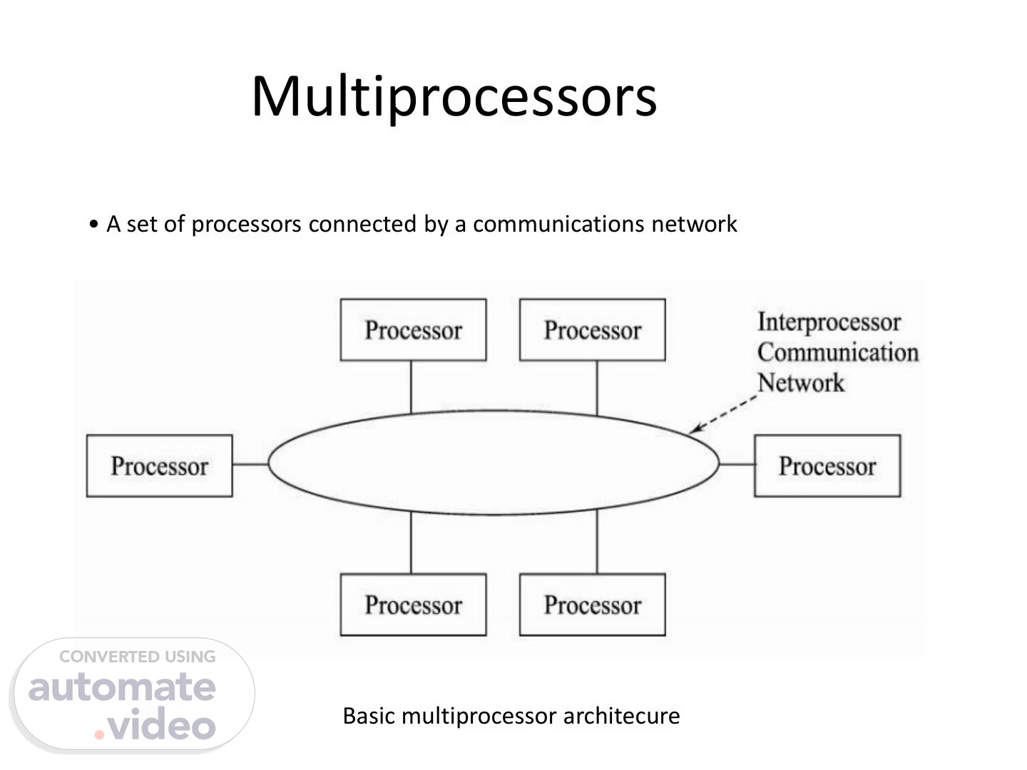
• A set of processors connected by a communications network Multiprocessors Basic multiprocessor architecure.
Scene 2 (7s)
• A multiprocessor system is an interconnection of two or more CPU’s with memory and input-output equipment. • Multiprocessors system are classified as multiple instruction stream, multiple data stream systems(MIMD). • There exists a distinction between multiprocessor and multicomputers that though both support concurrent operations. • In multicomputers several autonomous computers are connected through a network and they may or may not communicate but in a multiprocessor system there is a single OS Control that provides interaction between processors and all the components of the system to cooperate in the solution of the problem. • VLSI circuit technology has reduced the cost of the computers to such a low Level that the concept of applying multiple processors to meet system performance requirements has become an attractive design possibility..
Scene 3 (38s)
Taxonomy of mono- mulitporcessor organizations.
Scene 4 (44s)
Characteristics of Multiprocessors: Benefits of Multiprocessing: 1. Multiprocessing increases the reliability of the system so that a failure or error in one part has limited effect on the rest of the system. If a fault causes one processor to fail, a second processor can be assigned to perform the functions of the disabled one. 2. Improved System performance. System derives high performance from the fact that computations can proceed in parallel in one of the two ways: a) Multiple independent jobs can be made to operate in parallel. b) A single job can be partitioned into multiple parallel tasks. This can be achieved in two ways: - The user explicitly declares that the tasks of the program be executed in parallel - The compiler provided with multiprocessor s/w that can automatically detect parallelism in program. Actually it checks for Data dependency.
Scene 5 (1m 19s)
COUPLING OF PROCESSORS: Tightly Coupled System/Shared Memory: - Tasks and/or processors communicate in a highly synchronized fashion - Communicates through a common global shared memory - Shared memory system. This doesn’t preclude each processor from having its own local memory(cache memory) Loosely Coupled System/Distributed Memory - Tasks or processors do not communicate in a synchronized fashion. - Communicates by message passing packets consisting of an address, the data content, and some error detection code. - Overhead for data exchange is high - Distributed memory system Loosely coupled systems are more efficient when the interaction between tasks is minimal, whereas tightly coupled system can tolerate a higher degree of interaction between tasks..
Scene 6 (1m 47s)
Shared (Global) Memory - A Global Memory Space accessible by all processors - Processors may also have some local memory Distributed (Local, Message-Passing) Memory - All memory units are associated with processors - To retrieve information from another processor's memory a message must be sent there Uniform Memory - All processors take the same time to reach all memory locations Non-uniform (NUMA) Memory - Memory access is not uniform.
Scene 7 (2m 5s)
Shared and distributed memory.
Scene 8 (2m 11s)
Shared memory multiprocessor: Characteristics - All processors have equally direct access to one large memory address Space Limitations - Memory access latency; Hot spot problem.
Scene 9 (2m 21s)
Interconnection Structures: The interconnection between the components of a multiprocessor System can have different physical configurations depending n the number of transfer paths that are available between the processors and memory in a shared memory system and among the processing elements in a loosely coupled system. Some of the schemes are as: - Time-Shared Common Bus - Multiport Memory - Crossbar Switch - Multistage Switching Network - Hypercube System a. Time shared common Bus - All processors (and memory) are connected to a common bus or busses - Memory access is fairly uniform, but not very scalable - A collection of signal lines that carry module-to-module communication - Data highways connecting several digital system elements - Operations of Bus.
Scene 10 (2m 49s)
Memory Unit CPU 1 CPU 2 CPU 3 IOPI IOP 2 Time shared common bus organization Local Bus Common S hared Memory System Bus Controller Controller SYSTEM BUS CPU System Bus Controller Local Memory Local Memory IOP Local Bus Local Memory CPU Local Bus system bus structure for multiprocessor.
Scene 11 (2m 58s)
In the above figure we have number of local buses to its own local memory and to one or more processors. Each local bus may be connected to a CPU, an IOP, or any combinations of processors. A system bus controller links each local bus to a common system bus. The I/O devices connected to the local IOP, as well as the local memory, are available to the local processor. The memory connected to the common system bus is shared by all processors. If an IOP is connected directly to the system bus the I/O devices attached to it may be made available to all processors Disadvantage.: • Only one processor can communicate with the memory or another processor at any given time. • As a consequence, the total overall transfer rate within the system is limited by the speed of the single path.
Scene 12 (3m 34s)
b. Multiport Memory: Multiport Memory Module - Each port serves a CPU Memory Module Control Logic - Each memory module has control logic - Resolve memory module conflicts Fixed priority among CPUs Advantages: - The high transfer rate can be achieved because of the multiple paths. Disadvantages: - It requires expensive memory control logic and a large number of cables and connections.
Scene 13 (3m 52s)
c. Crossbar switch: - Each switch point has control logic to set up the transfer path between a processor and a memory. - It also resolves the multiple requests for access to the same memory on the predetermined priority basis. - Though this organization supports simultaneous transfers from all memory modules because there is a separate path associated with each Module. - The H/w required to implement the switch can become quite large and complex Advantage: - Supports simultaneous transfers from all memory modules Disadvantage: - The hardware required to implement the switch can become quite large and complex..
Scene 14 (4m 17s)
Memo modules MM2 MM3 MM4 Mill PIJI Memo Module data Multiplexers address arbitration RIW mem enable data,address, and control fron CPU I control from CPU 2 data address, and control from CPU 3 a) cross bar switch controlfromCPU4 b) Block diagram of cross bar switch.
Scene 15 (4m 28s)
d. Multistage Switching Network: - The basic component of a multi stage switching network is a two-input, two output interchange switch..
Scene 16 (4m 38s)
Using the 2x2 switch as a building block, it is possible to build a multistage network to control the communication between a number of sources and destinations. - To see how this is done, consider the binary tree shown in Fig. below. - Certain request patterns cannot be satisfied simultaneously..
Scene 17 (4m 53s)
- Some request patterns cannot be connected simultaneously. i.e., any two sources cannot be connected simultaneously to destination 000 and 001 - In a tightly coupled multiprocessor system, the source is a processor and the destination is a memory module. - Set up the path transfer the address into memory transfer the data - In a loosely coupled multiprocessor system, both the source and destination are Processsing elements..
Scene 18 (5m 13s)
e. Hypercube System: The hypercube or binary n-cube multiprocessor structure is a loosely coupled system composed of N=2n processors interconnected in an n-dimensional binary cube. - Each processor forms a node of the cube, in effect it contains not only a CPU but also local memory and I/O interface. - Each processor address differs from that of each of its n neighbors by exactly one bit position. - Fig. below shows the hypercube structure for n=1, 2, and 3. - Routing messages through an n-cube structure may take from one to n links from a source node to a destination node. - A routing procedure can be developed by computing the exclusive-OR of the source node address with the destination node address. - The message is then sent along any one of the axes that the resulting binary value will have 1 bits corresponding to the axes on which the two nodes differ. - A representative of the hypercube architecture is the Intel iPSC computer complex. - It consists of 128(n =7) microcomputers, each node consists of a CPU, a floating point processor,local memory, and serial communication interface units.
Scene 19 (5m 57s)
Inter-processor Arbitration - Only one of CPU, IOP, and Memory can be granted to use the bus at a time - Arbitration mechanism is needed to handle multiple requests to the shared resources to resolve multiple contention - SYSTEM BUS: o A bus that connects the major components such as CPU’s, IOP’s and memory o A typical System bus consists of 100 signal lines divided into three functional groups: data, address and control lines. In addition there are power distribution lines to the components. - Synchronous Bus o Each data item is transferred over a time slice o known to both source and destination unit o Common clock source or separate clock and synchronization signal is transmitted periodically to synchronize the clocks in the system - Asynchronous Bus o Each data item is transferred by Handshake mechanism - Unit that transmits the data transmits a control signal that indicates the presence of data - Unit that receiving the data responds with another control signal to acknowledge the receipt of the data o Strobe pulse -supplied by one of the units to indicate to the other unit when the data transfer has to occur.
Scene 20 (6m 39s)
Inter processor communication and synchronization: - The various processors in a multiprocessor system must be provided with a facility for communicating with each other. o A communication path can be established through a portion of memory or a common input- output channels. - The sending processor structures a request, a message, or a procedure, and places it in the memory mailbox. o Status bits residing in common memory o The receiving processor can check the mailbox periodically. o The response time of this procedure can be time consuming. - A more efficient procedure is for the sending processor to alert the receiving processor directly by means of an interrupt signal. - In addition to shared memory, a multiprocessor system may have other shared resources. o e.g., a magnetic disk storage unit. - To prevent conflicting use of shared resources by several processors there must be a provision for assigning resources to processors. i.e., operating system. - There are three organizations that have been used in the design of operating system for multiprocessors: master-slave configuration, separate operating system, and distributed operating system. - In a master-slave mode, one processor, master, always executes the operating system functions. - In the separate operating system organization, each processor can execute the operating system routines it needs. This organization is more suitable for loosely coupled systems. - In the distributed operating system organization, the operating system routines are distributed among the available processors. However, each particular operating system function is assigned to only one processor at a time. It is also referred to as a floating operating system..
Scene 21 (7m 39s)
Cache Coherence cache coherence is the consistency of shared resource data that ends up stored in multiple local caches. When clients in a system maintain caches of a common memory resource, problems may arise with inconsistent data, which is particularly the case with CPUs in a multiprocessing system. Shared Cache -Disallow private cache -Access time delay.
Scene 22 (7m 56s)
CACHE COHERENCE X = 52 Main memory Caches are Coherent x = 52 Cache Incoherency in Write Through x = 120 Cache Incoherency in Write Back Policy Bus X = 52 Processors X = 120 Main memory x = 52 x = 52 x = 52 x = 52 Main memory Bus . •.Caches Processors Bus X = 52 :Caches Processors.
Scene 23 (8m 8s)
Software Approaches * Read-Only Data are Cacheable - Private Cache is for Read-Only data - Shared Writable Data are not cacheable - Compiler tags data as cacheable and noncacheable - Degrade performance due to software overhead * Centralized Global Table - Status of each memory block is maintained in CGT: RO(Read-Only); RW(Read and Write) - All caches can have copies of RO blocks - Only one cache can have a copy of RW block Hardware Approaches * Snoopy Cache Controller - Cache Controllers monitor all the bus requests from CPUs and IOPs - All caches attached to the bus monitor the write operations - When a word in a cache is written, memory is also updated (write through) - Local snoopy controllers in all other caches check their memory to determine if they have a copy of that word; If they have, that location is marked invalid(future reference to this location causes cache miss).