Scene 1 (0s)
[Audio] Greetings of the day , Today we are going to discuss the flexural test on a beam using both two-point and three-point loading methods. This practical aims to determine the flexural strength of the material and to compare how different loading conditions affect the bending behavior of the specimen. Greetings of the day , Today we are going to discuss the flexural test on a beam using both two-point and three-point loading methods. This practical aims to determine the flexural strength of the material and to compare how different loading conditions affect the bending behavior of the specimen..
Scene 2 (36s)
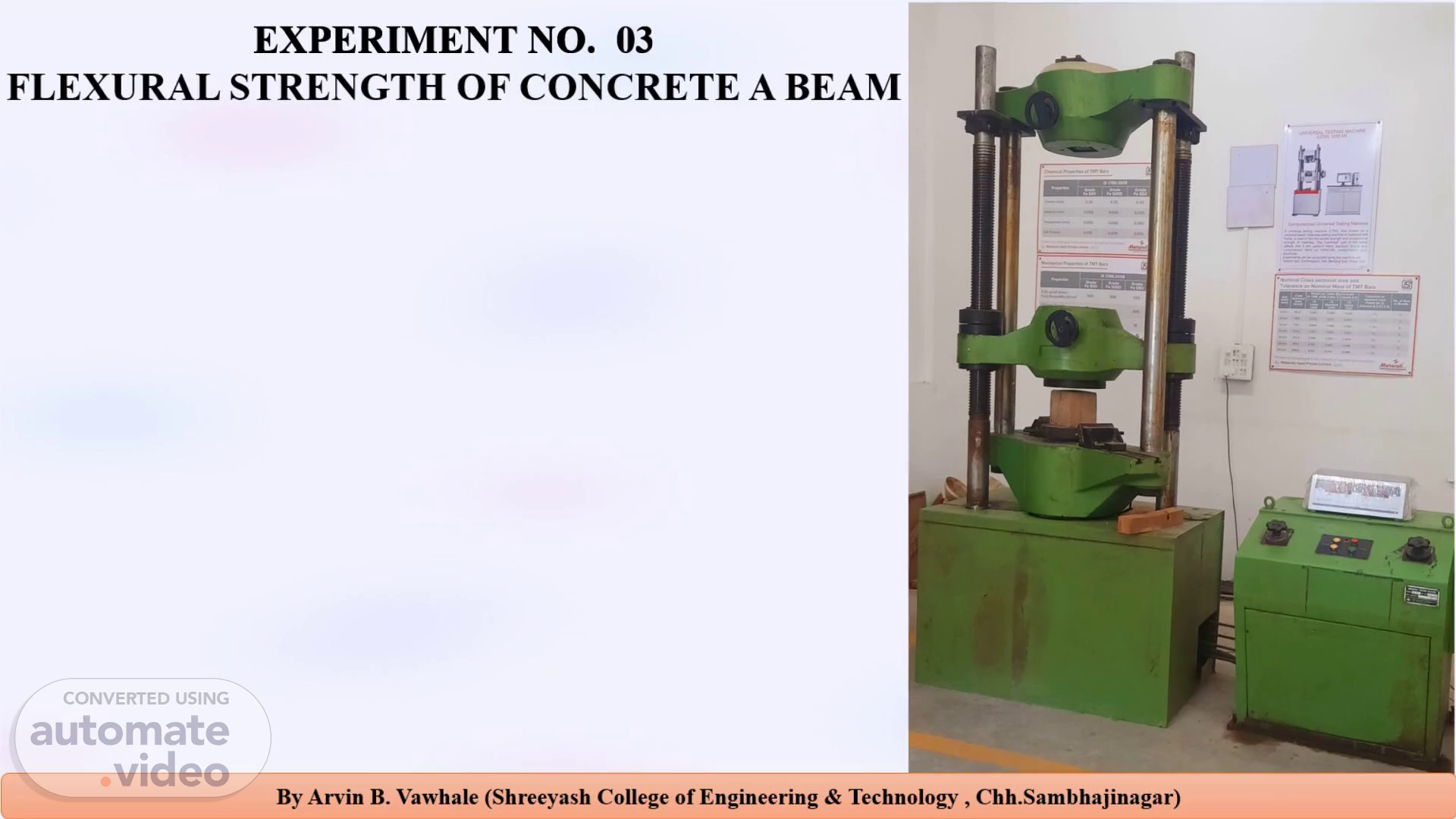
[Audio] EXPERIMENT Number . 03 FLEXURAL STRENGTH OF CONCRETE BEAM AIM: To determine the Flexural Strength of concrete beam (Modulus of Rupture) by using universal Testing Machine. APPARATUS: UTM, Concrete Beam of size 15 x 15x 70 cm (when size of aggregate is less than 38 mm) or of size 10 x 10 x 50 cm (when size of aggregate is less than 19 mm), Weighing Balance, Ruler Scale REFERENCE: Indian Standard 516:1959 (Reaffirmed 2004) - Method of Tests for Strength of Concrete. Indian Standard 456:2000 - Plain and Reinforced Concrete - Code of Practice.
Scene 3 (1m 31s)
[Audio] Theory :- The flexural strength of concrete, also known as the Modulus of Rupture (fᵣ), is a measure of an unreinforced concrete beam's ability to resist failure in bending. Significance: It is critical for designing pavements, slabs, and other structural elements where tensile stresses due to bending are predominant. Since concrete is weak in tension, its flexural strength is a key design parameter. Loading Method: This test is typically performed using a two-point loading system (also called third-point loading). This method ensures a constant bending moment between the two loading points, inducing a pure flexural failure in that region. Failure: The beam fails in tension on the bottom face (soffit) within the constant moment zone. The failure is sudden and brittle..
Scene 4 (2m 25s)
[Audio] Formula: The modulus of rupture is calculated using the following formula from Indian Standard 516: For a greater than 13.3 cm (for 150 mm beam): fᵣ = (P times l) by (b times d square) For a less than 13.3 cm but greater than 11.0 cm: fᵣ = (3 times P into a) by (2 times b into d square) Where: fr = Modulus of Rupture (Newton per mm square or Mega Pascal) P = Maximum load applied at failure (Newton) L = Supported span of the beam (millimeter) - Standard is 500milimeter for a 150 millimeter beam. b = Width of the beam (millimeter) d = Depth of the beam (millimeter) a = Distance between the line of fracture and the nearer support (millimeter) - Measured on the tension face..
Scene 5 (3m 32s)
[Audio] In this diagram The specimen is supported at two ends but loaded at two equal points (usually symmetrically placed). The bending moment is constant between the two loading points, producing pure bending (no shear in the central zone). Setup: Two supports + two equal loads at equal distances from the center. Formula (for bending stress): Stress is equal to 3Pa divide by b into d square where P = one of the applied loads, a = distance between support and load point. Three-Point Loading (or Three-Point Bending Test) The specimen (usually a beam) is supported at two ends and loaded at the center with a single downward force. It produces maximum bending moment at the center and is used to determine flexural strength or modulus of rupture. Stress is equal to 3PL by 2bd square where P = load at fracture, L = span length, b = width, d = depth of beam..
Scene 6 (4m 36s)
[Audio] PROCEDURE:- Measure the width (b) and depth (d) of the beam at the mid-span section to the nearest 0.2 mm. Record these values. 2. Examine the testing machine to ensure it is calibrated and functioning correctly. Place the beam in the testing machine symmetrically. The supported span (l) should be 500 millimeter. 3. The loading system must be a two-point loading setup, where the load is applied equally at two points, each located at one-third of the span from the supports. 4. Load Apply the load without shock and increase it continuously at a rate of 0.7 Mega Pascal /min (approx. 400 kg per min). 5. Continue loading until the specimen fails. Note the maximum load (P) at which the beam fractures. 6. Record the type of failure and the distance of the crack from the nearest support (a)..
Scene 7 (5m 38s)
[Audio] The table in the image shows the results of flexural tests conducted under two-point and three-point loading conditions on different beam specimens. It lists key parameters like: Span length (L): The distance between the supports during the test. Width (b) and Depth (d): Cross-sectional dimensions of the beam specimen. Maximum load (P): The highest load the specimen can withstand before failure. Flexural strength (σf): Calculated using standard formulas depending on whether it is a two-point or three-point loading test..
Scene 8 (6m 14s)
By Arvin B. Vawhale (Shreeyash College of Engineering & Technology , Chh.Sambhajinagar).
Scene 9 (6m 31s)
[Audio] PRECAUTIONS to be taken while performing experiment is :- The beam must be placed centrally and symmetrically on the supports. The load must be applied without any impact and at a constant rate. The distance a must be measured accurately after the test. And finally we got the RESULTs :- The average Flexural strength of given specimen = 6.002 newton per millimeters square.