ELC303A Single Phase Transformers
Scene 1 (0s)
[Audio] ELC303A Single Phase Transformers By: Chris and Jen Meloche.
Scene 4 (12s)
[Audio] What is a single-phase transformer? A single-phase transformer operates on single-phase power and has two parts - the magnetic and the electric parts. The magnetic transformer part consists of a magnetic iron core, while the electric part consists of a copper transformer. Only alternating current operates the transformer because direct current does not create an electromagnetic field. A transformer does not have any moving parts; hence, there is no mechanical friction when operating a single-phase transformer. Therefore, there are few energy losses when using a single-phase transformer, making the single-phase transformer highly efficient. When a transformer's primary winding encounters an alternating current, it generates an alternating electromagnetic field. A part of the generated magnetic field links with the secondary winding through mutual induction, producing a current. Voltage is induced in the secondary windings with the same frequency as primary windings. Faraday's Law can determine the value of the induced voltage..
Scene 5 (1m 24s)
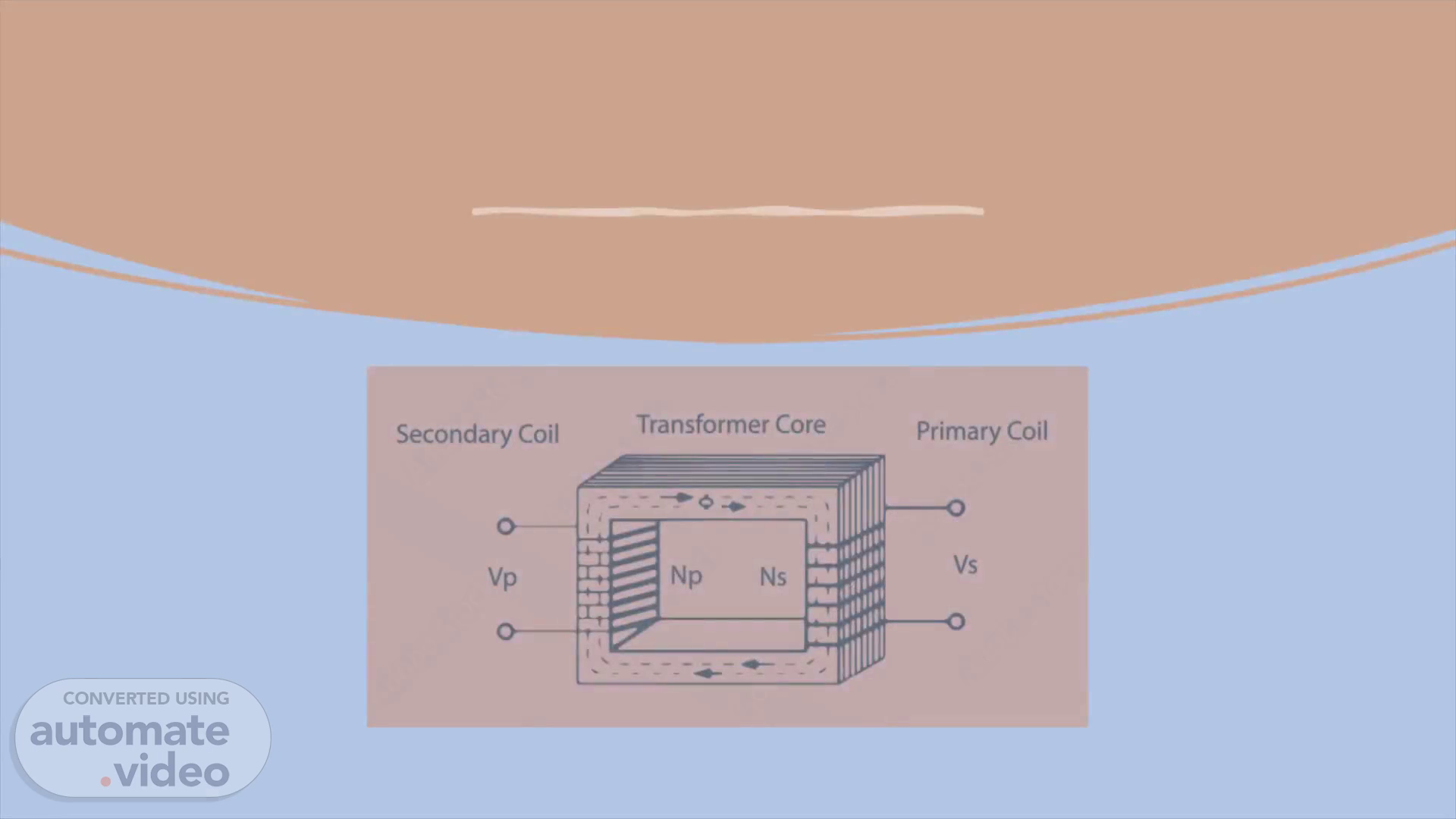
[Audio] Basic operation AC current passes through a coiled piece of wire This creates an expanding and collapsing magnetic field around the coil of wire There is a second coil of wire interlaced with the first coil The magnetic field imposes its influence on the second coil Magnetic Induction The magnetic field induces a force into the second coil A voltage meter across the second coil will indicate a voltage equal to the ratio of turns on the coils If there are more turns on the second coil then the voltage will be larger If there are less turns on the second coil then the voltage will be smaller.
Scene 6 (2m 13s)
[Audio] What is electromagnetic induction? Electromagnetic induction is the process by which a current can be induced to flow due to a changing magnetic field. The force on a current-carrying wire due to the electrons which move within it when a magnetic field is present is a classic example. This process also works in reverse. Either moving a wire through a magnetic field or (equivalently) changing the strength of the magnetic field over time can cause a current to flow..
Scene 7 (2m 45s)
[Audio] Construction of Single-Phase Transformer A single-phase transformer has two main parts: Core and Windings. There are many other parts in the construction of single-phase transformer. But core and windings are the key parts in single phase transformer construction. By using core and winding, along with insulation, we can construct a hands-on single-phase transformer..
Scene 8 (3m 15s)
[Audio] Series and Parallel In practice, the terminals on a transformer are mounted in a standard way so that the transformer has either additive or subtractive polarity, as illustrated in this Figure. A transformer is said to have additive when terminal H1 is diagonally opposite terminal X Similarly, a transformer has subtractive polarity when terminal H1 is adjacent to terminal Xl. The standard polarity designation for transformers is as follows: Transformers manufactured above 200 kVA will have subtractive polarities. Transformers with voltage ratings above 9,000 volts, regardless of the kVA rating, will have subtractive polarities. Transformers manufactured at or below 200 kVA with a voltage rating of 9,000 volts or less will have additive polarities. If transformer leads are unmarked, a polarity test can be made to identify and mark the leads. By convention, the top-left terminal when the transformer is looked at from its low voltage side is always labeled H1..
Scene 9 (4m 25s)
[Audio] Dual voltage transformer with its secondary windings connected in parallel. The H1 and H2 leads are labeled. Next, a jumper is connected between the H1 lead and the low-voltage lead adjacent to it, and a voltmeter is connected between H2 and the other low-voltage lead. A low voltage is then applied to the H1 and H2 leads and the voltmeter reading is recorded. If the voltmeter reading is greater than the applied voltage, the transformer is additive and XI will be the lead on the right. If the voltmeter reading is less than the applied voltage, the transformer is subtractive and X1 is on the left. In this polarity test, the jumper wire effectively connects the secondary voltage ES in series with the primary voltage E. Consequently, Es either adds or subtracts from E. From this you can see how the terms "additive" and "subtractive" are derived..
Scene 10 (5m 24s)
[Audio] Additive and Subtractive Polarity. Diagram, schematic Description automatically generated.
Scene 11 (5m 31s)
[Audio] The data on the Nameplate of a transformer contains of kVA rating, Voltage Rating, Frequency, Number of Phases, Temperature, Type of Cooling, % Impedance and Reactance, Name of Manufacture, Year of Manufacture etc..
Scene 12 (5m 47s)
[Audio] Transformer currents If there is no load attached to the secondary, then a very small current flows in the primary This current is called excitation current Consider what keeps the current very small Once a load is connected then the amount of secondary current controls the primary current The turns ratio will determine the value of the resulting primary current.
Scene 13 (6m 16s)
Transformer Connections.
Scene 14 (8m 56s)
[Audio] Single-Phase Transformers for Three-Phase Operation Single-phase transformers may be connected in groups in many ways for three-phase transformation. Fig. above shows a delta - delta group and Fig. below shows a wye - delta group. In general, groups with wye - delta connection, but without use of a fourth connection as a neutral, are to be avoided where unbalanced loads must be carried, because an unbalance in load will cause a circulating current of fundamental frequency to flow around the delta and will cause increased heating. If, however, in a wye - delta bank with ungrounded neutral a primary conductor be opened, as by blowing of a fuse, while the secondary is carrying a three-phase motor load, the bank will no longer attempt to maintain three-phase voltage at its secondary terminals and neither the primary nor the secondary winding will be overloaded. Under these conditions a three-phase motor on the secondary line will still operate single-phase and will attempt to carry its assigned load. The current in one motor line will be twice as large as that in either of the other two lines; and, if the motor is protected by overload relays in only two of its lines, then there is one chance in three that the motor will not be adequately protected against excessive current..
Scene 15 (10m 19s)
[Audio] Types Of Transformers The following slides cover transformer types that are commonly manufactured to accept and output single-phase AC power. The autotransformer In an autotransformer part of the energy is transferred by induction and the rest is by conduction. There are three types of auto transformers: step-up, step-down, and variable auto transformers which can be either step-up or step-down the voltage. Variable auto transformers are used in the laboratory and industry to provide a wide range of ac voltages from a single source. The above figures show step-up and step-down autotransformers. In the above Figures, the first winding is shown connected in an additive manner to the secondary winding. Now, the relationship between the voltage on the first winding and the voltage on the second winding is given by the turn's ratio of the transformer. However, the voltage at the output of the whole transformer is the sum of the voltage on the first winding and the voltage on the second winding. The first winding here is called the common winding, because its voltage appears on both sides of the transformer. The small winding is called the series winding, because it is connected in series with the common winding..
Scene 16 (11m 41s)
[Audio] Autotransformer: typically used in low power applications to connect circuits with different voltage classes. It contains only one winding, cannot isolate circuits, and is usually smaller, lighter, and cheaper than other transformers. The voltage source and electrical load are connected to two taps, and voltages are determined by tapping the winding at different points. An autotransformer with an adjustable tap is known as a variac or variable transformer. Normal transformer will have two windings which are physically separated but magnetically coupled together with the help of a magnetic core. As they are separately been isolated, they are called as primary winding which receives the voltage from the source and secondary winding which transfers to the output load. But the transformer in which there will be only one winding which is common to both primary and secondary is called Autotransformer. The term Auto here refers to that the voltage input variations will be automatically can be improved or can be reduced utilizing the single winding. Auto Transformers are used in applications where there is no requirement for electrical insulation between input and output windings..
Scene 17 (12m 58s)
[Audio] Constant-voltage transformer Constant-voltage transformer (CVT): these produce a relatively constant output voltage, despite potentially large variances in the input voltage..
Scene 18 (13m 14s)
[Audio] Instrument Transformer Instrument Transformers are used in AC system for measurement of electrical quantities i.e. voltage, current, power, energy, power factor, frequency. Instrument transformers are also used with protective relays for protection of power system. Basic function of Instrument transformers is to step down the AC System voltage and current. The voltage and current level of power system is very high. It is very difficult and costly to design the measuring instruments for measurement of such high level voltage and current. Generally measuring instruments are designed for 5 A and 110 V..
Scene 19 (13m 58s)
[Audio] The measurement of such very large electrical quantities, can be made possible by using the Instrument transformers with these small rating measuring instruments. Therefore these instrument transformers are very popular in modern power system. Advantages of Instrument Transformers The large voltage and current of AC Power system can be measured by using small rating measuring instrument i.e. 5 A, 110 – 120 V. By using the instrument transformers, measuring instruments can be standardized. Which results in reduction of cost of measuring instruments. More ever the damaged measuring instruments can be replaced easy with healthy standardized measuring instruments. Instrument transformers provide electrical isolation between high voltage power circuit and measuring instruments. Which reduces the electrical insulation requirement for measuring instruments and protective circuits and also assures the safety of operators. Several measuring instruments can be connected through a single transformer to power system. Due to low voltage and current level in measuring and protective circuit, there is low power consumption in measuring and protective circuits..
Scene 20 (15m 15s)
[Audio] What is instrument transformer? Instrument transformer has 2 types Current transformer Potential transformer.
Scene 21 (15m 28s)
[Audio] Current Transformer (C.T.) Current transformer is used to step down the current of power system to a lower level to make it feasible to be measured by small rating Ammeter (i.e. 5A ammeter). A typical connection diagram of a current transformer is shown in figure below. Primary of C.T. is having very few turns. Sometimes bar primary is also used. Primary is connected in series with the power circuit. Therefore, sometimes it also called series transformer. The secondary is having large no. of turns. Secondary is connected directly to an ammeter. As the ammeter is having very small resistance. Hence, the secondary of current transformer operates almost in short circuited condition. One terminal of secondary is earthed to avoid the large voltage on secondary with respect to earth. Which in turns reduce the chances of insulation breakdown and also protect the operator against high voltage. More ever before disconnecting the ammeter, secondary is short circuited through a switch 'S' as shown in figure above to avoid the high voltage build up across the secondary..
Scene 22 (16m 50s)
[Audio] Potential Transformer (P.T.) Potential transformer is used to step down the voltage of power system to a lower level to make is feasible to be measured by small rating voltmeter i.e. 110 – 120 V voltmeter. Primary of P.T. is having large no. of turns. Primary is connected across the line (generally between on line and earth). Hence, sometimes it is also called the parallel transformer. Secondary of P.T. is having few turns and connected directly to a voltmeter. As the voltmeter is having large resistance. Hence the secondary of a P.T. operates almost in open circuited condition. One terminal of secondary of P.T. is earthed to maintain the secondary voltage with respect to earth. Which assures the safety of operators..
Scene 23 (17m 49s)
[Audio] Few differences between C.T. and P.T. are listed below Current Transformer (C.T.) Connected in series with power circuit. Secondary is connected to Ammeter. Secondary works almost in short circuited condition. Primary current depends on power circuit current. Primary current and excitation vary over wide range with change of power circuit current One terminal of secondary is earthed to avoid the insulation break down. Secondary is never be open circuited. Potential Transformer (P.T.) Connected in Parallel with Power circuit. Secondary is connected to Voltmeter. Secondary works almost in open circuited condition. Primary current depends on secondary burden. Primary current and excitation variation are restricted to a small range. One terminal of secondary can be earthed for Safety. Secondary can be used in open circuit condition..
Scene 24 (19m 0s)
[Audio] Advantages and Disadvantages Advantages are; The system is reliable and service continuity ensures when transformers are connected in parallel Transformers work in parallel, reducing the possibility of overloading The transformer can switch on or off based on the load demand Disadvantages are; It is costly to maintain It requires a lot of installation space There is a chance of failure when transformers are connected in parallel.
Scene 25 (19m 38s)
[Audio] Conclusion When deciding on whether to use a single-phase or three-phase transformer, you should consider the operating frequency range, voltage rating of the windings, power rating, secondary current rating and temperature requirements. A key advantage to single-phase vs. three-phase transformers is lower cost. Three-phase transformers are used in high power systems, while single-phase transformers are more appropriate for lighter equipment. The single-phase transformer is a very versatile and essential piece of equipment in many industries. By understanding the different parts of the transformer, you can better maintain and operate this critical piece of machinery. The single-phase transformer is composed of the following parts: the core, the primary winding, the secondary winding, the insulation, and the yoke. Each part plays an important role in transformer operation. By understanding the function of each component, you can keep your transformer running smoothly for years to come..
Scene 26 (20m 45s)
[Audio] THE END We hope you enjoyed this video!. THE END.