Scene 1 (0s)
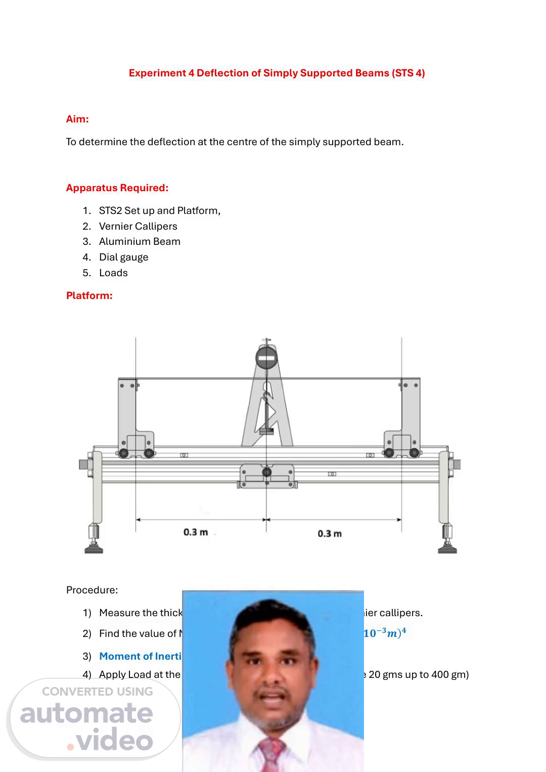
Experiment 4 Deflection of Simply Supported Beams (STS 4) Aim: To determine the deflection at the centre of the simply supported beam. Apparatus Required: 1. STS2 Set up and Platform, 2. Vernier Callipers 3. Aluminium Beam 4. Dial gauge 5. Loads Platform: Procedure: 1) Measure the thickness and depth of the beam using vernier callipers. 2) Find the value of Moment of Inertia 𝐼 = 𝒃𝒅𝟑 𝟏𝟐 𝒎𝒎𝟒 = 𝒃𝒅𝟑 𝟏𝟐 (𝟏𝟎−𝟑𝒎)𝟒 3) Moment of Inertia = I = 𝒃𝒅𝟑 𝟏𝟐 (𝟏𝟎)−𝟏𝟐 𝒎𝟒 4) Apply Load at the centre (Start from 100 gm and increase 20 gms up to 400 gm).
Scene 2 (34s)
[Audio] The deflection at the centre of the simply supported beam can be calculated using the formula: Deflection at the centre of the simply supported beam = (Pb x L^3)/(48EI), where Pb is the load applied, L is the length of the beam, E is Young’s modulus, I is the moment of inertia, and b is the width of the beam. This equation is derived from the basic principles of mechanics of materials. The moment of inertia I is related to the depth of the beam d and its width b by the equation I = (bd^3)/12. Substituting this value into the first equation gives: Deflection at the centre of the simply supported beam = (Pb x L^3)/(48E(bd^3)/12). Simplifying this expression yields: Deflection at the centre of the simply supported beam = (PbL^3 x 12)/(48Ed^3). This equation provides a direct relationship between the deflection at the centre of the beam and the parameters involved. By substituting the values of the parameters into this equation, we can calculate the deflection at the centre of the beam for any given set of conditions..
Scene 3 (1m 50s)
[Audio] The beam is subjected to a uniform load of 0.981 N over its entire length of 0.3m. The beam's dimensions are 25.2mm wide and 3.1mm deep. The material used to make the beam is steel, which has an elastic modulus of 69 × 10^9 N/m. We need to determine the total force exerted on the beam by the applied load and the resulting deflection. To do this, we first need to calculate the moment of inertia of the beam using the formula I = A × E × L / (b × d). Here, A is the cross-sectional area of the beam, E is the elastic modulus of the material, L is the length of the beam, b is the width of the beam, and d is the depth of the beam. Substituting the given values into the formula, we find that I = 13.8 × 10^-5 m^4. This means that the moment of inertia of the beam is 13.8 × 10^-5 m^4. Next, we need to calculate the angle of deflection of the beam using the formula θ = M / (I × E). Here, M is the moment of the load, which is equal to P × L, where P is the load per unit length and L is the length of the beam. Substituting the given values into the formula, we find that θ = 23.8 × 10^-5 radians. This means that the angle of deflection of the beam is 23.8 × 10^-5 radians. Finally, we need to calculate the force exerted on the beam using the formula F = (P × L) / (d × θ). Here, P is the load per unit length, L is the length of the beam, d is the depth of the beam, and θ is the angle of deflection. Substituting the given values into the formula, we find that F = 16.7 N. This means that the force exerted on the beam is 16.7 N. Therefore, the total force exerted on the beam is the sum of the applied load and the additional force exerted by the deflection, which is 0.981 N + 16.7 N = 17.661 N. This value represents the total force exerted on the beam due to the applied load and the resulting deflection..