TOWING / TAKEN IN TOW
Scene 1 (0s)
TOWING / TAKEN IN TOW. .
Scene 2 (7s)
Towing equipment and tools. Methods of towing disabled ship. Emergency towing arrangement. Contents of the emergency towing booklet. Procedures for towing in good and rough weather conditions. Calculation of bollard pull and towing speed prior towage. Communication ..
Scene 3 (23s)
[Audio] REQUIREMENTS FOR ARRANGEMENTS & COMPONENTS In accordance with Resolution IMO A535( 13) & MSC. 35( 63) The emergency towing arrangements should be so designed as to facilitate salvage and emergency towing operations on tankers primarily to reduce the risk of pollution. The arrangements should at all times be capable of rapid deployment in the absence of main power on the ship to be towed and easy connection to the towing vessel..
Scene 4 (57s)
Strength of the towing components: 1. Towing components as specified in 2.2 for strength should have a working strength of at least 1,000 kN for tankers of 20,000 tonnes deadweight and over but less than 50,000 tonnes deadweight and at least 2,000 kN for tankers of 50,000 tonnes deadweight and over(working strength is defined as one half ultimate strength). The strength should be sufficient for all relevant angles of towline, i.e. up to 90° from the ship’s centerline to port and starboard and 30° vertical downwards. 2. Other components should have a working strength sufficient to withstand the load to which such components may be subjected during the towing operation..
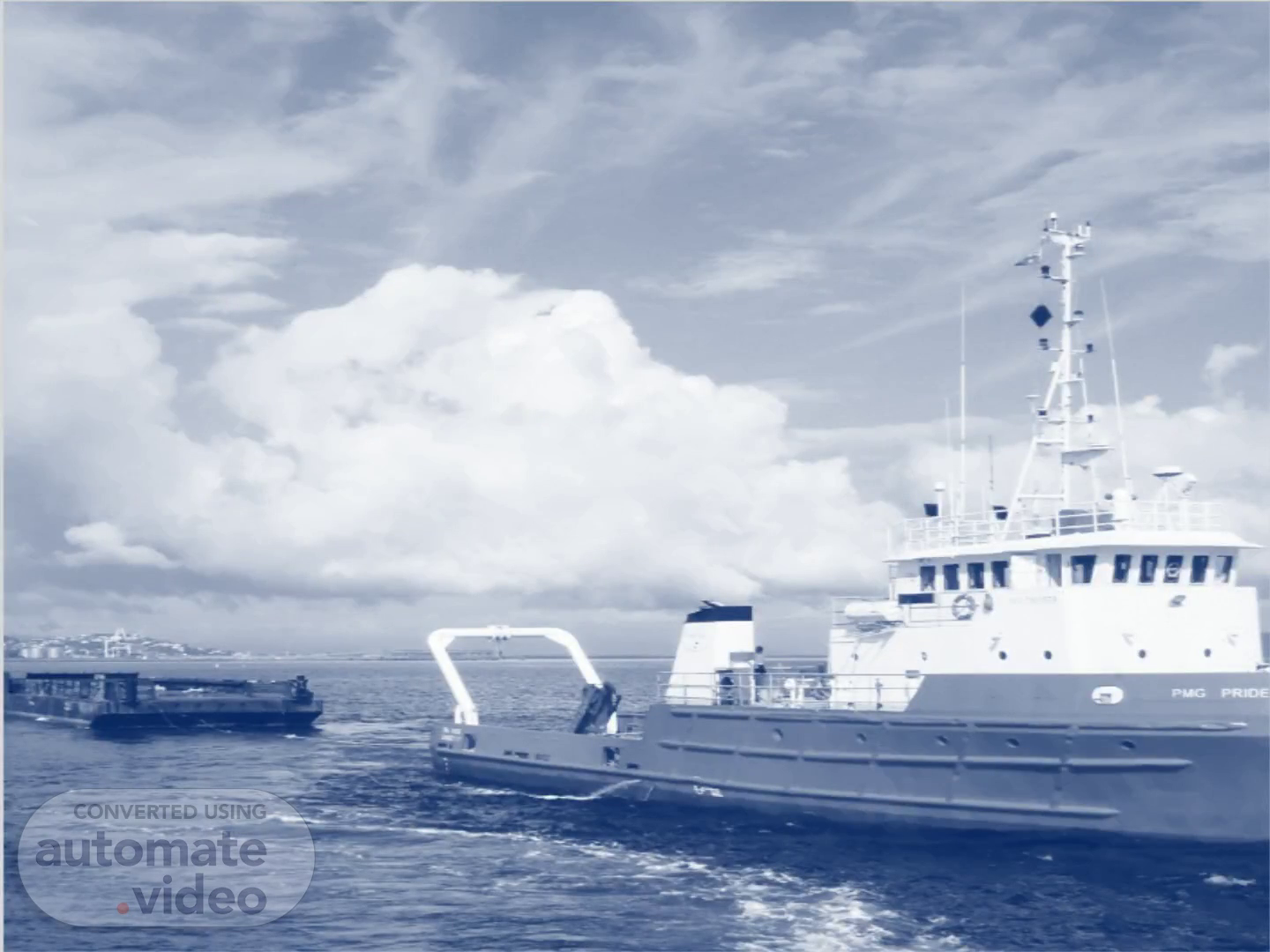
Scene 5 (1m 28s)
Towing Components The major components of the towing arrangements should consist of the following:.
Scene 6 (1m 48s)
Fairlead Chafing Chain Storage Box AFT Pick-Up Gear Towing Pennant Strong Point Storage Drum FORWARD Towing Pennant Fairlead Triangle Plate Strong Point Chafing Chain.
Scene 7 (1m 55s)
Pick Up Gear Box: 1. The box containing the pick-up gear is to be fitted on the rail of the ship, close to the fairlead and the box contains the following items. Pick up chain – fitted with a connecting link for attaching to the shackle passing through the cable thimble. Stainless Steel Pickup Buoy with light Polypropylene Pickup Cable Additional equipments also includes but not limited to; Pick Up Line Messenger Line Withdrawal Line Retrieval Wire Pull Back Bit Buoy.
Scene 8 (2m 19s)
Fairleads: 1. Fairleads should have an opening large enough to pass the largest portion of the chafing gear, towing pennant or towing line. 2. The fairlead should give adequate support for the towing pennant during towing operation which means bending 90°to port and to starboard side and 30°vertical downwards. The vending ratio (towing pennant bearing surface diameter to towing pennant diameter should be not less than 7 to 1.) 3. The fairlead should be located as close as possible to the deck and, in any case, in such a position that the chafing chain is approximately parallel to the deck when it is under strain between the strongpoint and the fairlead..
Scene 9 (2m 48s)
Location of strongpoint and fairlead: The bow and stern strongpoint and fairleads should be located so as to facilitate towing from either side of the bow or stern and minimize the stress on the towing system. Chaffing Chain: 1. The Chafing chain is a STUD LINK chain used for the standard connection between the strongpoint and a standard pear-shaped open link allowing connection to a standard bow shackle. 2. The chafing chain should be stowed in such a way that it can be rapidly connected to the strong point. 3. The chafing chain should be long enough to ensure that the towing pennant remains outside the fairlead during the towing operation. A chain extending from the strongpoint to a point at least 3 m beyond the fairlead should meet this criterion..
Scene 10 (3m 20s)
Special end Link 95mm dia Enlar Lin Shackle Mooring havvser 170 370 Thimble 267 mm 130 327 Type Not less than 24 cornmon links (24mm x 304mm = 7296mm) 96mm dia hole : Oblong plate 170 mm : 100 Pick up rope 76mrn stud link chain Chain manufactured, tested and inspected in accordance With 'ACS W22 0b Iona late. material: cast steel BS EN f0393:200S or plate steel material to BS EN1002S-1 :200a (or equivalent) SWL PR load 59T BR load 84T Shackle in material: BS E N' 826M aoPGr•ade U or equivalent Shackle bow, material: BS EN 10083-1:2006 60SM 36 Grade T or equivalent SWL42T PR load BR load 70mm MBL tonne 611.7 497.8 53mm dia hole 76mm • mm 350 mm Taper pins 96 102 51 mm 51 mm Size 76mm 76mm Grade per IACS W22 SWL tonne 250 200 The number and size Of Chafe chains used should be determined by the terminal operator after an analysis Of the maxirnum mooring loads. If necessary, weak links or quick release devices should be incorporated into the mooring system..
Scene 11 (3m 55s)
Towing pennant: 1. The towing pennant should have a hard eye-formed termination allowing connection to a standard bow shackle. 2. Towing pennants are connections used to easily connect the apex of the ship to the tugboat’s towing line the Apex side is connected with the chain pennant and the other side that is the chain pennant is connected to towing wire. 3. Its length should be two times the lightest seagoing ballast free board at fairlead + 50m..
Scene 12 (4m 17s)
Smith Bracket Storage Box for Towing Pennant Chock Stainless Steel pickup Buoy with light Chock Roller Pedestal Towing Pennant.
Scene 13 (4m 25s)
Method of Towing a disabled ship. General 1.The Master of the ship should determine the towing pattern in consultation with the towing company. 2. The ships should be towed from the bow as far as possible. If it is not possible to tow from the bow for some reasons such as grounding, collision, towing from the stern may be selected as an alternative. 3.Following circumstances are to be taken into the Master’s account. a) Ship’s position b) Availability of the propulsion system c) Direction and rate of drift d) Distance and estimated time to any possible groundinglocation e) Weather and sea conditions f) Short-term marine forecast for the area of the incident.
Scene 14 (4m 54s)
Pattern 1-F (Towing from the bow): Use a hawser or a wire rope and a bollard.
Scene 15 (5m 6s)
Pattern 2-F (Towing from the bow) Use wire ropes or chains and two bollards in order to distribute the towing force..
Scene 16 (5m 19s)
Pattern 3-F (Towing from the bow) Use hawsers of the ship..
Scene 17 (5m 30s)
Pattern 1-A (Towing from the stern) Use a hawser or a wire rope and a bollard..
Scene 18 (5m 43s)
Pattern 2-A (Towing from the stern) Use hawsers of the ship..
Scene 19 (5m 54s)
Emergency Towing Arrangements. As per SOLAS - International Convention for the Safety of Life at Sea Chapter II-1 - Construction - Structure, subdivision and stability, machinery and electrical installations. Part A-1 - Structure of ships Regulation 3.4 - Emergency towing arrangements on tankers. Emergency towing arrangements shall be fitted at both ends on board every tanker of not less than 20,000 tonnes deadweight. For tankers constructed on or after 1 July 2002: 1. the arrangements shall, at all times, be capable of rapid deployment in the absence of main power on the ship to be towed and easy connection to the towing ship. At least one of the emergency towing arrangements shall be pre-rigged ready for rapid deployment; and 2. emergency towing arrangements at both ends shall be of adequate strength taking into account the size and deadweight of the ship, and the expected forces during bad weather conditions. The design and construction and prototype testing of emergency towing arrangements shall be approved by the Administration, based on the Guidelines developed by the Organization. For tankers constructed before 1 July 2002, the design and construction of emergency towing arrangements shall be approved by the Administration, based on the Guidelines developed by the Organization..
Scene 20 (6m 44s)
As per SOLAS the Emergency Towing Procedures applies to the following ships. All passenger ships not later than 1 Jan 2010 Cargo ships constructed on or after 1 Jan 2010 Cargo ships constructed before 1 Jan 2010, not later than 1 Jan 2012 Ships shall be provided with a ship specific emergency towing procedure. Such a procedure shall be carried on board for use in emergency situations and shall be based on existing arrangements and equipments onboard the ship. The procedure shall include Drawings of fore and aft deck showing emergency towing arrangements. Inventory of equipment onbd that can be used for emergency towing. Means and methods of communication Sample procedures to facilitate the preparation and conducting of emergency towing. The ETS should have fore and aft arrangements to enable the ship To be towed in an emergency or to tow another ship in emergency..
Scene 21 (7m 19s)
Ready availability of towing arrangements : 1. To facilitate approval of such equipment and to ensure rapid deployment, emergency towing arrangements should comply with the following criteria: The aft emergency towing arrangement should be pre-rigged and be capable of being deployed in a controlled manner in harbor conditions in not more than 15 min. The pick-up gear for the aft towing pennant should be designed at least for manual operation by one person taking into account the absence of power and the potential for adverse environmental conditions that may prevail during such emergency towing operations. The pick-up gear should be protected against the weather and other adverse conditions that may prevail. The forward emergency towing arrangement should be capable of being deployed in harbor conditions in not more than 1 h. The forward emergency towing arrangement should be designed at least with a means of securing a towline to the chafing gear using a suitably positioned pedestal roller to facilitate connection of the towing pennant. Forward emergency towing arrangements which comply with the requirements for aft emergency towing arrangements may be accepted. All emergency towing arrangements should be clearly marked to facilitate safe and effective use even in darkness and poor visibility. 2. All emergency towing components should be inspected by ship personnel at regular intervals and maintained in good working order..
Scene 22 (8m 11s)
Emergency Towing Booklet According to SOLAS II-1, Reg. 3-4 and MSC.1/Circ. 1255.
Scene 23 (8m 45s)
Table of Contents: General Description 1.1. General 1.1.1. Flag or Class Approval 1.2. Limitation During Towing Operations 1.3. Master’s Action 1.4. Safety Considerations Principal Details 2.1. Ship 2.1.1. General Particulars 2.1.2. Radio Equipment 2.1.3. Power Supply 2.1.4. Existing Towing Equipment 2.2. Locations of the ETB 2.3. Training Education 2.4. Supporting Documents Procedures 3.1 Decision Matrix 3.2 Towing 3.3 Forecastle 3.3.1 Towing Pattern 1-F 3.3.2 Towing Pattern 2-F.
Scene 24 (9m 17s)
3.3.3 Towing Pattern 3-F 3.4 Poop Deck 3.4.1 Towing Pattern 1-A 3.4.2 Towing Pattern 2-A Appendix 4.1. Current Status 4.2. Communication Board 4.3. Tasks/Duties and Equipment.
Scene 25 (9m 33s)
Tow plan : Planning and preparation before a tow commences might include: Assessing the size and type of vessels or barges to be towed and any limitations of the tow. Confirmation that the tug is of suitable; size, manning, sea-keeping, horse power (HP) and bollard pull (BP). Tow wire and towing equipment is suitable for the planned tow. Route to be taken and passage planned, including safe transit times (day/night transits), times when passing through narrows, under bridges or areas of high traffic density, tight bends in rivers and adjacent river berths. Noting any areas of reduced depth, tidal limitations and currents expected during the voyage. A list of bridges with maximum and minimum height; tide height for each arch to be passed under showing the bridge’s maximum air-drafts..
Scene 26 (10m 7s)
Weather forecasts to include outlook for at least 48 hours. Confirmation of sufficient fuel, water, spares on board. Navigational information and warnings. Recommended speeds to comply with river regulations. Connection and disconnection arrangements. Stability of the tug and towed unit. Emergency contingency plans..
Scene 27 (10m 23s)
Safety considerations during Towing Operation:. 1st Officer / Chief Officer on mooring deck should be in contact with the Bridge in all times. Everyone on deck should be equipped with the personnel life saving appliance, and be alert for slips, trips and fall hazards. All crew should be informed well of the work procedures and tasks. When the towing line begins strained in tension, all on-deck staffs should be evacuated to the safe location. It is necessary to grease up continuously in order to prevent wear of ropes in chocks when wire ropes are used as towing lines. Wear-out condition in chocks should be constantly checked. Whilst engaged in towing operations the minimum number of crew essential to carry out duties, is to be on deck, and never exposed to a rope or wire under tension or load. Wherever possible, a "clear deck" of crew should be in operation whilst towing..
Scene 28 (11m 2s)
Limitation during towing operations :. Not all ships have the same degree of shipboard equipment, so that there may be limits to possible towing procedures. Nevertheless, the intention of this booklet is to predetermine what can be accomplished. The towing load should not exceed safety working loads of deck fitting. When heavy weather where the towing load increases significantly is forecasted, special considerations are to be paid to towing speed, towing lines arrangement and ship’s stability. When the angle of tow line around bow or stern chock becomes smaller, the resultant force acting on the chock gets greater. Therefore, tow line’s fleet angle around chocks should be kept greater than generally 135 degrees. When the fleet angle is expected to get smaller during turning operation, etc, towing speed should be sufficiently rated down. Loading points on stand-rollers are so high that great bending moments are generally transferred to the supporting structures. Stand-rollers are not to be used in towing lines arrangement..
Scene 29 (11m 44s)
Calculation of Bollard Pull and towing speed prior towage.
Scene 30 (12m 19s)
Towing Speed :. Vessels should never be towed at or above their hull speed . Hull speed or displacement speed is the speed at which the wavelength of a vessel's bow wave is equal to the waterline length of the vessel. Theoretical displacement hull speed is calculated by the formula: Velocity in knots = 1.35 x the square root of the waterline length in feet . At such a speed, fuel consumption rises considerably, and enormous strain is put on the towline and fittings as the towline tries to literally drag the vessel up and through its own bow wave. Not only does the risk of pulling out a fitting or snapping the towline increase, there have also been numerous instances of small vessels swamped and sunk while under tow purely because it was towed at excessive speed. Calculation for Towing Speed: Approx Max towing speed = Sq root of waterline length in feet x 1.34. Safe towing speed = 90% of approx Max speed..
Scene 31 (12m 59s)
Communication. Communications are a vital component of safe towage operations. It is essential that those onboard the vessel and the tug(s) are able to communicate promptly throughout the towage operation. Prior to towing operations being undertaken, the Master, Tugmaster (s ) should establish suitable means of communication, exchange relevant information (e.g. speed of vessel), and agree a plan for the towage operation. A communications plan for contacting the salvage/towing ship should be made prior towage. This plan should list all information that the ship’s master needs to communicate to the salvage/towing ship. This list should include but not be limited to: Damage or seaworthiness; Status of ship steering; Propulsion ;.
Scene 32 (13m 29s)
On deck power systems; On-board towing equipment; Existing emergency rapid disconnection system; Forward and aft towing point locations; Equipment , connection points, strong points and safe working loads (SWL ); Towing equipment dimensions and capacities; and Ship particulars;.
Scene 34 (13m 48s)
I 2 3 4 5 6 8 9 10 11 12 13 14 15 Person Captain 9 Quartermaster 1 g Offiær 2 ngÉ1eer Bosun Deckman A Dækman B Chief Engirmr Elætrician Equiprnonts o o o o 0 o o o o o o o o o o o o o Task Communcaton With tovang shp, Overall gx•rson Assistant to Captain with Bridge. on dæk Assistant to I Winch & Mooring Winch handling Rope handing in engtne ECR Assistant to Chief.