Bone Augmentation in Implant Dentistry: A Step-by-Step Guide to Predictable Alveolar Ridge and Sinus Grafting - Michael A. Pikos, Richard J. Miron - (2019) 272 pp., ISBN: 9780867158250 part 5
Scene 1 (0s)
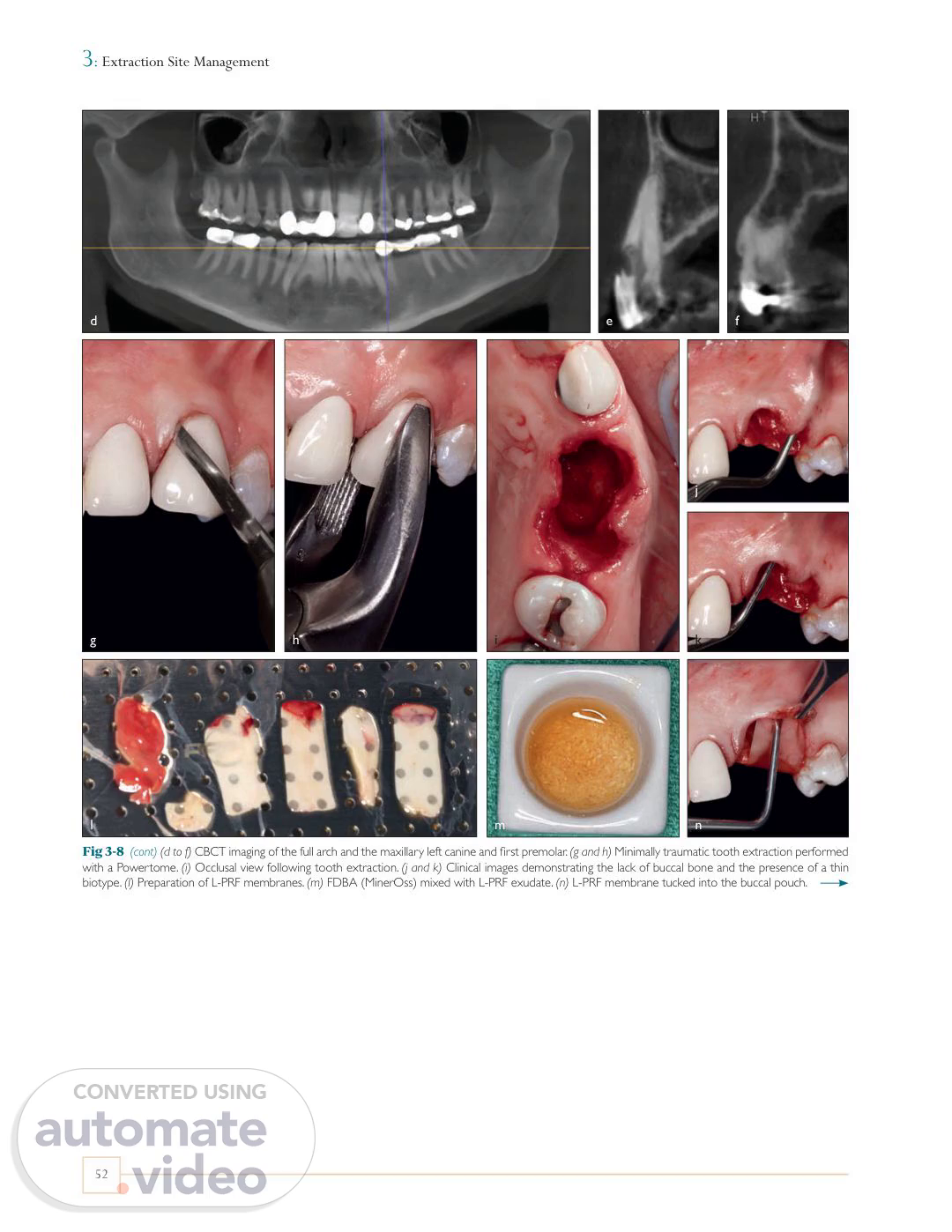
[Virtual Presenter] 3 : Extraction Site Management d e f j g h i k l m n Fig 3-8 (cont) (d to f) CBCT imaging of the full arch and the maxillary left canine and first premolar. (g and h) Minimally traumatic tooth extraction performed with a Powertome. (i) Occlusal view following tooth extraction. (j and k) Clinical images demonstrating the lack of buccal bone and the presence of a thin biotype. (l) Preparation of L-PRF membranes. (m) FDBA (MinerOss) mixed with L-PRF exudate. (n) L-PRF membrane tucked into the buccal pouch. 52.
Scene 2 (42s)
[Audio] Single-Tooth Alveolar Ridge Preservation in the Nonesthetic Zone o p q r s t u v Fig 3-8 (cont) (o and p) FDBA is placed with moderate condensation within the extraction socket. Note: In this case, L-PRF was available, and thus a membrane was used experimentally in lieu of a dPTFE membrane. The same subperiosteal pouch approach was used. Today, some clinicians utilize L-PRF plugs for graft containment and promotion of soft tissue closure. (q) Occlusal view of the grafted sites. (r) Intact L-PRF membrane. (s) Final sutures. (t and u) Suture removal at 2 weeks. Notice the excellent soft tissue healing. (v and w) Labial and occlusal views at 4 months. (x and y) Radiographs of both sites demonstrating adequate mineralized tissue in the grafted sites. w x y 53.
Scene 3 (1m 41s)
[Audio] 3 : Extraction Site Management z cc aa dd bb ee ff gg hh ii jj Fig 3-8 (cont) (z) Flap elevation. (aa) Implant placement followed by secondary grafting with MinerOss to supplement the buccal and lingual bone deficiencies that were not completely maintained with L-PRF. (bb) Implant coverage with L-PRF membranes to favor soft tissue regeneration. (cc) Healing abutments were inserted through the L-PRF membranes via a poncho technique. (dd) Final sutures. (ee) Three months postoperative, the healing abutments were removed prior to final crown restoration. (ff and gg) Clinical images 5 years postoperative. (hh to jj) CBCT imaging after 5 years demonstrating excellent facial bone thickness. Note: In this case, the lack of appropriate embrasure space between the canine and premolar resulted in a blunted papilla despite having favorable facial bone maintenance. This case highlights the importance of appropriate contour to allow for optimal peri-implant soft tissue drape. Of importance to note, however, is that the papilla between two adjacent implants, despite optimal embrasure form, will often be deficient in height. Furthermore, a second grafting procedure was required due to incomplete graft incorporation as a result of the inability of the L-PRF membrane to act as a stable barrier. Based on the results from this case as well as others, L-PRF as a barrier membrane cannot be recommended, especially in cases with thin and/or compromised facial plate deficiencies. A number of cases also present with a periapical abscess and compromised buccal and/or lingual plates, either partial or complete. In such cases, a typical GBR technique is used where a membrane is utilized to prevent soft tissue infiltration. When marked bone loss is observed on either the buccal or lingual surfaces, typically recombinant human growth factors are utilized to facilitate regeneration. It is important to note that while both rhPDGF-BB (GEM 21S) and rhBMP-2 (Infuse Bone Graft) are capable of stimulating bone formation, the potency of rhBMP-2 is far superior because of its osteoinductive potential. Nevertheless, cost is certainly a factor, as rhPDGF-BB can be obtained for about $200, whereas rhBMP-2 costs upward of $600 (as of 2019). As a rule of thumb, when the entire buccal plate is missing, 54.
Scene 4 (4m 19s)
[Audio] Single-Tooth Alveolar Ridge Preservation in the Nonesthetic Zone a d b c e f Maintain papilla Extraction site Sulcular incisions X Fig 3-9 Use of rhPDGF (GEM 21S) following extraction of a mandibular first molar with a missing buccal plate. (a) Clinical image demonstrating a pocket depth greater than 10 mm with the presence of a fistula. (b to d) CBCT images demonstrating resorption of the buccal plate. (e) Following full flap reflection, notice the loss of the buccal plate. (f) Occlusal view of the resulting bone defect. Note: In cases with facial plate compromise greater than 3 mm, it is important to include a surface releasing incision one full tooth anterior to the extraction site (including the papilla), along with sulcular incisions one full tooth mesial and distal (g). g Surface releasing incision a standard approach to ridge preservation includes the use of a titanium-reinforced dPTFE membrane with fixation combined with an allograft (MinerOss) and rhPDGF (Fig 3-9). When most of the alveolar structure is missing, such as when the patient lacks both buccal and lingual bone and pre- sents with severe bone loss, the same regenerative procedure is performed with rhBMP-2 instead of rhPDGF because of its superior osteoinductive potential and the greater need for the regenerative capacity of the defect (Fig 3-10). Because rhBMP-2 has the ability to induce ectopic bone formation, it is essential that rhBMP-2 always be combined with its supplied absorbable collagen sponge (ACS) for 15 minutes prior to its application. As a rule of thumb, a healing period of 7 months is typically warranted when rhBMP-2 is utilized. 55.
Scene 5 (6m 18s)
[Audio] 3 : Extraction Site Management i h j k m o n p l q r s t Fig 3-9 (cont) (h) A titanium-reinforced dPTFE membrane is fixed with two screws (Pro-fix, Osteogenics). (i and j) FDBA with rhPDGF (GEM 21S) is moderately condensed into the socket. (k) The dPTFE membrane is then sutured into place utilizing the subperiosteal membrane pouch protocol. Note: While rhPDGF (GEM 21S) is commercially available with its β-tricalcium phosphate (β-TCP) carrier, an allograft is most often utilized because of its superior osteoconductive and resorption properties. (l) CBCT image at 5 months demonstrating new bone formation, notably on the previously deficient buccal surface. (m) Membrane exposure at the buccal-crestal line angle. Partial membrane removal was done at 2 months (see note below). (n) Clinical image at 5 months following full flap reflection. (o) Membrane removal; notice the excellent ridge width. (p) Implant placement. Note: Often at the 2-month mark, the dPTFE membrane is elevated from the lingual pouch and cut at the buccal-crestal line angle and removed. This is done in cases where primary closure is not obtained (most of the time) to prevent further inflammation that often occurs beyond 2 months when the dPTFE membrane is exposed to the oral cavity, resulting in an accumulation of plaque. A more conservative method to remove the remaining dPTFE membrane at 5 months is via permucosal stab incisions for screw removal followed by an envelope incision access at the crest.(q) Note the healthy peri-implant soft tissue at 3 months after implant placement. (r and s) Clinical images at 5 years. (t) Periapical radiograph demonstrating excellent bone volume maintenance. Note: In this case, an additional month (5 months instead of 4) was needed for complete graft incorporation because the buccal plate was fully compromised. Based on clinical observations comparing identical defects treated with and without rhPDGF, the bone quality with rhPDGF is more dense at re-entry at the same time frame. The relative additional cost of adding this growth factor is justified by the necessity to regenerate greater bone volume and increase density at re-entry (see chapter 2). 56.
Scene 6 (8m 54s)
[Audio] Single-Tooth Alveolar Ridge Preservation in the Nonesthetic Zone a b c d e Fig 3-10 Use of rhBMP-2 (Infuse Bone Graft) for the regeneration of a severely compromised maxillary left first molar. (a) Clinical photograph of the maxillary left first molar. (b) Radiographic image demonstrating severe bone loss on both the buccal and palatal surfaces. (c to e) Following flapless tooth extraction, a curette was utilized to demonstrate the severely resorbed ridge involving both buccal and palatal plates. (f) rhBMP-2/absorbable collagen sponge (ACS; Infuse Bone Graft) was mixed with a 1:1 mixture by volume of corticocancellous bone allograft (MinerOss). (g and h) A titanium-reinforced dPTFE membrane was utilized, and the defect was grafted with the rhBMP-2/allograft complex. (i) Membrane secured and final sutures placed. Note: This case demonstrates the loss of both buccal and palatal plates, thus necessitating greater osteoinductive potential and hence the use of rhBMP-2/ACS. If only one plate were missing, the less-expensive recombinant protein (rhPDGF) would be used. In this case, no flaps were reflected, thus allowing for optimal biologically based regeneration via the intact periosteum with its osteogenic properties. Typically, the titanium-reinforced PTFE membrane would be secured via tack or screw placement. In this case, no fixation was used in an attempt to provide for a minimally invasive approach. Today, it is prudent to have some fixation to provide immobility of the membrane in cases where the buccal and palatal plates are compromised. f g h i 57.
Scene 7 (10m 46s)
[Audio] 3 : Extraction Site Management j k n l m o p q r s Fig 3-10 (cont) (j) After a healing period of 7 months with rhBMP-2, the titanium-reinforced dPTFE membrane demonstrated exposure. (k) CBCT imaging revealed excellent new bone gain in both the horizontal and vertical directions. Note: In cases where the dPTFE membrane is not fixed, membrane removal should be done at 6 to 8 weeks postoperative. However, in this case the patient was lost to follow-up for 6 months, and the membrane exfoliated from the lingual pouch but remained in the buccal pouch. This highlights the importance of relatively early membrane removal when no membrane fixation is used. Despite the membrane not being removed at 2 months, excellent bone formation was observed both clinically and radiographically. (l) Following flap reflection, note the excellent bone formation. (m to o) A core sample of bone was obtained with a trephine. The core sample histologically demonstrated excellent new bone formation (type 2) at 7 months. (p) Implant placement. (q) Healing after 4 months, just prior to crown fabrication. (r) Clinical photograph at 5 years. (s) CBCT image demonstrating excellent marginal bone stability. 58.
Scene 8 (12m 12s)
[Audio] Single-Tooth Alveolar Ridge Preservation in the Esthetic Zone PERI-IMPLANT ESTHETICS Low risk Five diagnostic keys High risk More coronal or lingual More apical or facial Tooth position / FGM 1 1 Flat scallop High scallop Gingival form 2 2 Thick Thin Biotype 3 3 Square Triangular Tooth shape 4 4 High crest Low crest Osseous crest position 5 5 Outcome More likely to be favorable More likely to be unfavorable Fig 3-11 Diagnostic criteria for single-tooth implants in the esthetic zone and peri-implant esthetic risk assessment as defined by Kois.54 FGM, free gingival margin. to create diagnostic parameters to treat patients requiring tooth extraction in the esthetic zone because of these drastic differences according to tissue biotype. Single-Tooth Alveolar Ridge Preservation in the Esthetic Zone Five diagnostic keys In a study conducted by Kois in 2001, five key diagnostic keys were reported.54 He acknowledged that the creation of an esthetic implant restoration with gingival architecture that harmonizes with the adjacent dentition is a formidable challenge in the esthetic zone. It was highlighted that the predictability of the peri-implant esthetic outcome may ultimately be determined by the patient's own presenting anatomy rather than the clinician's ability to manage stateof-the-art procedures. To guide clinicians, five diagnostic keys were revealed54 (Fig 3-11): 1. Relative tooth position 2. Form of the periodontium 3. Biotype of the periodontium 4. Tooth shape 5. Position of the osseous crest Extraction sites in the esthetic zone are far more prone to dimensional changes over time. It has previously been shown that the majority of extraction sites in the anterior maxilla demonstrate thin (< 1 mm) labial plates when examined via different means.6,52,53 With advancements made in the field of CBCT, CBCT images can be superimposed over various time points in the healing period. Utilizing this technology, Chappuis et al investigated the dimensional changes occurring postextraction following an 8-week healing period, corresponding with early implant placement.6 It was found that 69% of human cases presented with a buccal wall surface thinner than 1 mm. Furthermore, it was observed that after an 8-week healing period, an average vertical bone loss of 5.2 mm was reported.6 However, if the buccal bone thickness was greater than 1 mm, an average of only 1.1 mm of buccal bone loss was found. When the buccal bone was less than 1 mm (in the majority of cases), a resulting 7.5 mm of bone loss was observed. It therefore becomes highly essential 59.
Scene 9 (14m 11s)
[Audio] 3 : Extraction Site Management Characteristics of thick gingiva include the following: Relatively flat soft tissue and bony architecture Dense, fibrotic soft tissue Relatively large amount of attached gingiva Thick underlying osseous form Relatively resistant to acute trauma Reacts to disease with pocket formation and infrabony defect formation Characteristics of thin gingiva include the following: Highly scalloped soft tissue and bony architecture Delicate, friable soft tissue Minimal amount of attached gingiva Thin underlying bone characterized by bony dehiscence and fenestration Reacts to insults and disease with gingival recession Relative tooth position The hopeless tooth must be evaluated based on its relative position to the remaining dentition in three planes of space. These include its vertical, facial, and mesial planes. Each plane has the ability to influence the presenting configuration of the gingival architecture. In the vertical plane, a minimum of 2 mm of apical migration of the facial free gingival margin (FGM) may occur during pontic site development, and up to 1 mm of apical migration of the facial FGM will occur during immediate implant site development.55 In summary, a hopeless tooth with an FGM 1 to 2 mm coronal to the harmonious facial gingival position will result in a more favorable final esthetic result. In the faciolingual plane, a tooth positioned too facially will typically present with a thin or nonexistent labial plate. It therefore becomes preferable to graft the area both before and after extraction. If the tooth is too far lingual, a thicker labial plate may exist, and grafting may be considered more favorable before extraction.54 Tooth shape Three basic tooth shapes will influence peri-implant esthetics: square, ovoid, and triangular. The impact is both coronal to the FGM (the tooth shape will influence the volume and height of the gingival embrasure) and apical (the tooth shape will influence the proximity of the roots and support of the gingival tissue both facially and interproximally). The square tooth is the most favorable, and the triangular tooth is least favorable.56 There are two concerns regarding the mesiodistal tooth position: (1) the proximity of adjacent teeth necessary for providing proximal support and volume of the interdental papilla, and (2) the inclination, which contributes to proximal support but also influences the position of the contact point. Teeth with close root proximity possess thin interproximal bone, creating a greater risk of lateral resorption, which may impact interproximal bone width. Ideally, interproximal bone width should be at least 1.5 mm at the crest before extraction.56 Form of the periodontium Three categories of gingival scallop have previously been presented: high, normal, and flat. The average or normal gingival scallop is positioned 4 to 5 mm more incisally than the FGM.57,58 In a healthy periodontium, the underlying bony crest is 2 mm apical to the cementoenamel junction (CEJ) and follows the scallop of the CEJ. The greater this discrepancy, the higher the scallop and the higher the risk for gingival loss after extraction. In contrast, the flatter scallop tends to mimic the osseous crest, creating less discrepancy and more predictable maintenance of the interproximal papilla.54 Position of the osseous crest The osseous crest is a critical foundation for gingival levels. The greater the distance to the FGM, the.
Scene 10 (17m 57s)
[Audio] Single-Tooth Alveolar Ridge Preservation in the Esthetic Zone Table 3-1 Management guidelines for evaluating tissue degradation Time to implant placement Defect Labial plate loss Treatment 3–4 mm Mild 6 mm MBA, CTG; reevaluate; MBG, CTG 7–10 months MBA, mineralized bone allograft; FGG, free gingival graft; CTG, connective tissue graft; MBG, mandibular block graft. Fig 3-12 Summary illustration depicting the necessity of having a maximum of 5 mm between the tip of the papilla and the underlying bone. Furthermore, the distance between the CEJ on the restorative crown and the cervical portion of the implant should ideally be no greater than 3 to 4 mm. In addition, Class 1 interproximal height of bone is required for predictable regeneration of the alveolus.62 Protocol for soft and hard tissue regeneration With the profession's increasing focus on conservative esthetic dentistry, single-tooth implant reconstruction has become the therapy of choice for tooth replacement in the presence of adjacent healthy natural dentition and dentoalveolar tissues. In contrast to the posterior singletooth implant, the esthetic zone single-tooth implant can provide myriad technical, surgical, and regenerative challenges for the surgeon directly proportional to localized clinical pathology and remaining hard and soft tissue extraction socket architecture. In an ongoing effort to restore and mimic nature, this section presents a sequential management protocol for anterior single-tooth extraction sites that can result in predictable tissue regeneration appropriate to the demands of an optimized esthetic zone implant rehabilitation. Single-tooth implant reconstruction in the esthetic zone is a very demanding task. The esthetic and functional requirements for a successful long-term result often involve hard and soft tissue regeneration and can challenge even the most experienced implant dentist.64 Clinical extraction site management Extraction site management is based on the extent of alveolar bony tissue loss as previously categorized into mild, moderate, and severe vertical labial plate compromise65 (Table 3-1). A minimum labial plate thickness of 2 mm is recommended for an optimal esthetic and functional result with all cases, regardless of category. Periodontal biotype will impact clinical management of the specific osseous defect. Mild tissue degradation in the presence of a thick, flat periodontal biotype is characterized by less than 3 mm of vertical labial plate loss. Management consists of socket grafting with mineralized bone allograft and a free gingival graft (FGG)66,67 (Fig 3-13). A 4-month healing period is necessary before implant placement. This protocol is modified in the presence of a thin, highly scalloped biotype, where a connective tissue graft (CTG) is recommended in place of an FGG to help increase soft tissue volume.68 If the labial plate is less than 2 mm thick, then a bone xenograft is used as a veneer graft. Moderate tissue degradation in the presence of a thick or thin biotype is characterized by labial plate loss of 3 to 6 mm. Surgical management includes socket grafting with mineralized bone allograft and use of a CTG (Fig 3-14). This may result in sufficient hard.
Scene 11 (21m 44s)
[Audio] 3 : Extraction Site Management a b c d e f g h i j k l m n p o q r s t Fig 3-13 Extraction and delayed implant replacement of a failing maxillary right central incisor with a thick, flat periodontal biotype with less than 3 mm of vertical labial plate loss. (a) Preoperative labial view. (b) Periapical radiograph of the hopeless tooth. (c and d) Minimally traumatic tooth extraction. (e) Curettage of the extraction socket. (f and g) Mineralized allograft (FDBA, MinerOss) utilized to graft the extraction socket. (h) Final sutures with an FGG. (i and j) Provisional restoration. (k) Healing at 4 months. Notice the soft tissue adaptation. (l) CBCT radiograph demonstrating excellent bone volume. (m) Flap elevation via envelope design. (n and o) Crestal bone plasty to allow for optimal emergence profile. (p) Implant placement with veneer bone grafting performed with a xenograft (Bio-Oss, Geistlich) via a full-thickness facial pouch to maintain implant esthetics, improve contour, and maintain adequate facial plate thickness long term. (q) Final sutures. (r) Final provisional restoration. (s) Healing abutment removed at 3 months postoperative. (t) Final crown. Note: An FGG was used in this case because of the thick tissue biotype and the lack of need for increased soft tissue height. In this case, a dPTFE membrane could have been used instead of an FGG. However, we must keep in mind that with this type of membrane, there would be no increase in tissue thickness or maintenance of the gingival zenith as compared to an FGG plug or connective tissue graft. Also note that the FGM of the maxillary right central incisor is more apical than that of the left central incisor. This occurred despite the increased tissue volume obtained with the FGG solely because of overcontouring of the provisional restoration, resulting in apical tissue migration. In other words, an undercontoured provisional restoration would have maintained the grafted tissue volume, which would have provided a more optimized result. Finally, there is good stability of the gingival zenith not only because of the existing thick biotype but also because of the underlying veneer bone graft with xenograft. Today I would use a non-crosslinked membrane to better contain the veneer graft. This would be done with periosteal release within the pouch to allow for slight flap advancement. 62.
Scene 12 (24m 25s)
[Audio] Single-Tooth Alveolar Ridge Preservation in the Esthetic Zone a b c d e f g h i j k l m n o Fig 3-14 Extraction and implant replacement in a case with moderate tissue degradation in the presence of a thin biotype characterized by labial plate loss of 3 to 6 mm. (a to c) Minimally traumatic tooth extraction. (d to g) Curettage. Notice the lack of buccal bone. (h) Deepithelialization of crestal tissue with a microblade. (i) Occlusal view demonstrating thin facial bone. (j to n) Harvesting of an FGG. Note: It is important to not exceed a depth of 1.5 to 2.0 mm with this graft harvest. Deeper penetration results in increased postoperative discomfort. (o) Removal of adipose tissue from FGG. (p and q) Use of a radiosurgery device for hemorrhage control. p q 63.
Scene 13 (25m 22s)
[Audio] 3 : Extraction Site Management r t s u v w x y z Fig 3-14 (cont) (r and s) Fabrication of an L-PRF plug. (t) L-PRF plug inserted into the donor site. Note: This is done to accelerate soft tissue wound healing and minimize patient morbidity. (u to w) L-PRF membranes inserted into previously created subperiosteal buccal pouch. (x and y) Extraction socket grafted with mineralized allograft premixed with rhPDGF (GEM 21S). (z) Final sutures with an FGG. Note: Although 5.0 nylon sutures were used in this case, over the past 3 years I have been using 6.0 nylon.(aa and bb) Provisional restoration. Note the suturing of the donor site. (cc and dd) Healing of the recipient and donor sites at 1 week. aa bb cc dd 64.
Scene 14 (26m 19s)
[Audio] Single-Tooth Alveolar Ridge Preservation in the Esthetic Zone ee ff gg hh ii jj kk ll mm nn oo pp qq rr ss tt uu Fig 3-14 (cont) (ee to gg) Healing of the recipient and donor sites at 3 weeks. (hh and ii) Healing of the recipient site at 3.5 months. Note the slight loss of ridge dimension. (jj) CBCT image demonstrating adequate bone volume for implant placement. (kk to pp) Flap elevation, crestal bone plasty, and implant bed preparation with osseodensification burs. (qq) Implant placement. (rr) Veneer grafting with a xenograft (Bio-Oss). (ss to uu) External vertical mattress suture with PTFE 3.0 suture. 65.
Scene 15 (27m 5s)
[Audio] 3 : Extraction Site Management vv ww xx yy zz aaa Fig 3-14 (cont) (vv) Final sutures. (ww) Provisional restoration. (xx) View 6 months postoperative. (yy) View 10 months postoperative. (zz) Final crown. Note the pleasing esthetic result. (aaa) Final CBCT image. Notice the facial bone thickness utilizing this technique. Note: In this case, several suture types were used. Typically, over the past 3 years I have used 3.0 and 4.0 dPTFE sutures for esthetic zone work along with 5.0 and 6.0 polypropylene sutures for FGGs. These two materials are very kind to the soft tissues and repel plaque accumulation. a b c d e f g h i j Fig 3-15 Extraction and implant replacement in a site with severe tissue degradation characterized by complete labial plate loss. (a and b) Following tooth extraction, notice the complete loss of labial bone and the fistulous tract. (c) A CTG harvested from the palate was used for increased tissue thickness along with fistulous tract repair. (d and e) CTG sutured buccally within the defect area with a 5.0 nylon mattress suture. Note: It is important to use a large needle (FS2) in order to access the socket from the apical aspect of the mucosa. It is also important to have the needle entry at least 2 mm apical to the final position of the CTG. (f and g) Mineralized allograft was condensed into the socket, and the lingual flap margin of the CTG was positioned into the lingual pouch and secured with a 5.0 nylon mattress suture. (h) Final sutures with provisional restoration. (i) Clinical image 6 months postoperative. (j) Periapical radiograph 6 months postoperative. Note: Whenever there is a facial plate compromise greater than 3 mm, I add an additional month of healing time prior to re-entry. This is to allow adequate time for more complete bone graft incorporation. 66.