Scene 1 (0s)
AlMansoori Production Services Issue Date: 2nd Feb 2020 Surface Well Testing Document Number: MPS/SWT/SOP19_02 Standard Operating Procedures Rev. No. Page No. Air Compressor 02 1 of 15 Air Compressor CONTROLLED COPY: Copyright © ALMANSOORI Production Services. Printed copies of this document are considered uncontrolled. Unauthorized reproduction of this document is prohibited..
Scene 2 (30s)
[Audio] AlMansoori Production Services Issue Date: 2nd Feb 2020 Surface Well Testing Document Number: MPS/SWT/SOP19_02 Standard Operating Procedures Rev. No. Page No. Air Compressor 02 2 of 15 Document Revision History Rev. Number Date Description of Change Affected Pages By 00 01st Mar 1998 First Issue All MPS 01 29th April 2012 Total Update All MPS 02 31st Mar 2020 Total Update with new skeleton All MPS CONTROLLED COPY: Copyright © ALMANSOORI Production Services. Printed copies of this document are considered uncontrolled. Unauthorized reproduction of this document is prohibited..
Scene 3 (1m 21s)
[Audio] AlMansoori Production Services Issue Date: 2nd Feb 2020 Surface Well Testing Document Number: MPS/SWT/SOP19_02 Standard Operating Procedures Rev. No. Page No. Air Compressor 02 3 of 15 Table of Contents 1. Introduction: .................................................................................................................................................................................... 4 2. Purpose: ............................................................................................................................................................................................ 4 3. Policy: ................................................................................................................................................................................................ 4 4. Compressor (startup / shutdown) procedure: ............................................................................................................................... 4 4.1 Startup procedure: ..................................................................................................................................................................... 4 4.2 Shutdown procedure: ................................................................................................................................................................ 5 5. Safety Clips/whip check on Air Rubber Hoses:............................................................................................................................. 5 6. Checks Prior Starting Diesel Engine of Air Compressor: ............................................................................................................ 5 7. Whenever Re Fueling: ..................................................................................................................................................................... 5 8. Starting the Engine .......................................................................................................................................................................... 6 8.1 Ingersoll rand air compressor ................................................................................................................................................... 6 Starting Engine .......................................................................................................................................................................... 6 Stopping the Engine .................................................................................................................................................................. 7 Emergency Shutdown (Engine Stop) ....................................................................................................................................... 8 Re Starting Engine Post Emergency Shutdown ..................................................................................................................... 8 8.2 Atlas Copco Air Compressors ................................................................................................................................................... 9 Control Panel ............................................................................................................................................................................. 9 Specific Starting Procedure .................................................................................................................................................... 10 Power On/Off ........................................................................................................................................................................... 11 Starting ..................................................................................................................................................................................... 11 Warming Up ............................................................................................................................................................................ 12 Loading .................................................................................................................................................................................... 13 Stopping ................................................................................................................................................................................... 14 Emergency Stop ....................................................................................................................................................................... 15 Attachments: Air Compressor maintenance / Inspection Checklist (F 068/99) Daily Check List For Air Compressor (F 767) CONTROLLED COPY: Copyright © ALMANSOORI Production Services. Printed copies of this document are considered uncontrolled. Unauthorized reproduction of this document is prohibited..
Scene 4 (2m 55s)
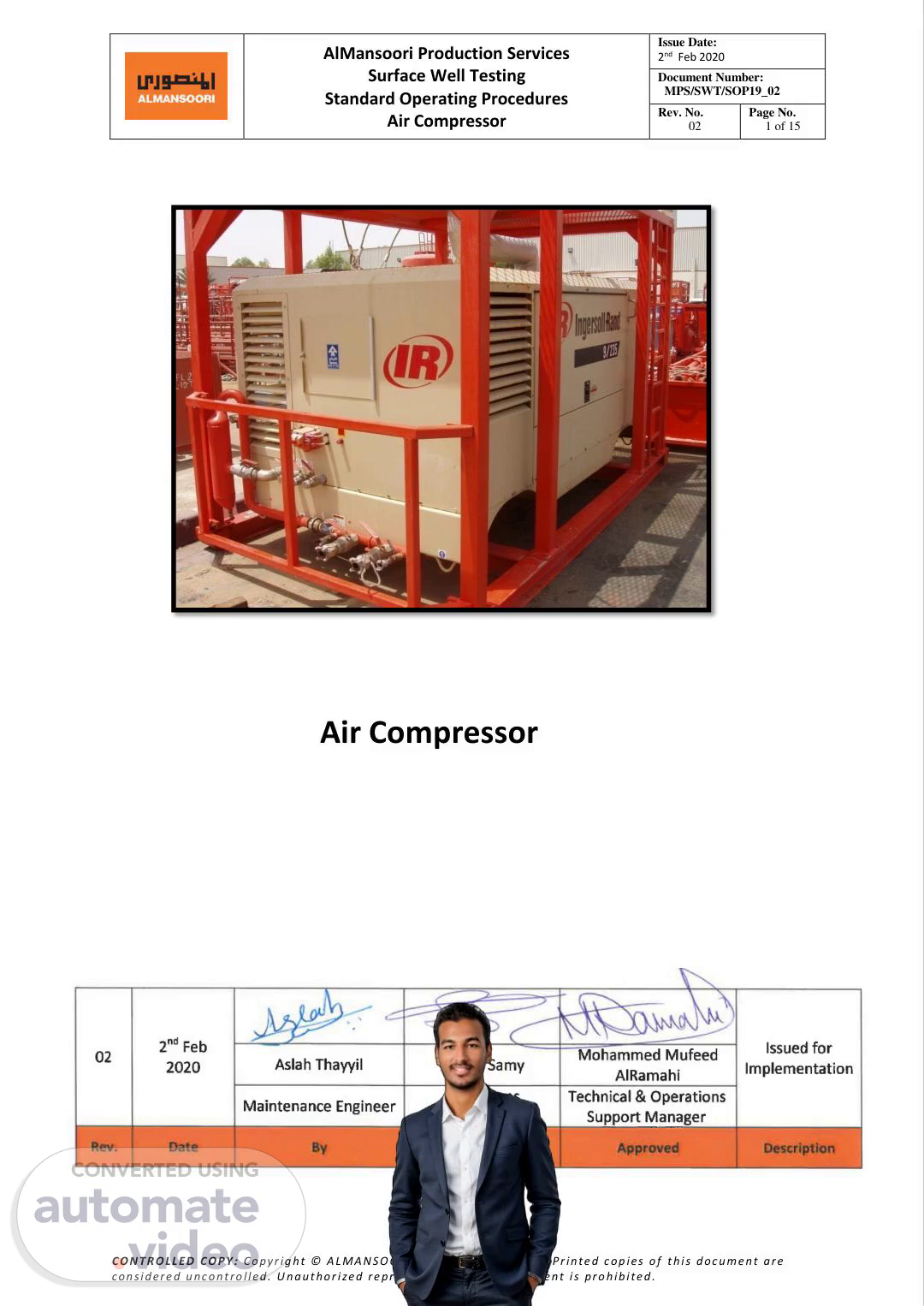
[Audio] AlMansoori Production Services Issue Date: 2nd Feb 2020 Surface Well Testing Document Number: MPS/SWT/SOP19_02 Standard Operating Procedures Rev. No. Page No. Air Compressor 02 4 of 15 1. Introduction: Diesel engine operated air compressors are mainly manufactured and supplied to AlMansoori with different capacities in terms of air pressures and air flow rates (80psig/120psig & 375SCFM/850SCFM respectively). Air compressors are being utilized to provide many aspects of support mainly to supply instrument air for separator scrubber, diaphragm pumps and to atomize green burner heads while burning muddy crude oil. Accordingly, certain procedures are required to be followed to ensure that the compressor will continue functioning to support the required purposes. 2. Purpose: This operating procedure is established to provide guidelines and detailed descriptions to properly rig up and operate Diesel engine operated air compressors, without causing any harm to personnel, assets and environment in line with H-S-E-Q policy & procedures. 3. Policy: This procedure covers all types of Diesel engine operated air compressors, in line with standard operating procedures, in which might be required in surface well testing for offshore/onshore rig and rigless, operations and installations. 4. Compressor (startup / shutdown) procedure: 4.1 Startup procedure: 1. Walk around the compressor to make sure everything is safe. 2. Open all the compressor doors. 3. Visually check for (loose fitting, worn hoses, fan belts, water leaking, oil leaking, et cetera) 4. Preparing the compressor for operation: 5. Checking oil level for engine and compressor 6. Checking the battery condition and connection 7. Checking the fuel level 8. Checking cooling water level 9. Battery switch ON. 10. Go to operation control panel. 11. Move the ignition switch to position 1. 12. Wait for few seconds (5-10 Sec). 13. Move the ignition switch to startup position and hold for few seconds (5-10 Sec) for engine starts up. 14. Wait (5 minutes) for engine to warm up. 15. Load the compressor (push load button) and check the compressor pressure (8 Bar). 16. Wait (3 minutes) and make sure the connections are safe and then gradually open the main air valve to scrubber and to instruments or to green burner for atomizing flaring. CONTROLLED COPY: Copyright © ALMANSOORI Production Services. Printed copies of this document are considered uncontrolled. Unauthorized reproduction of this document is prohibited..
Scene 5 (6m 14s)
[Audio] AlMansoori Production Services Issue Date: 2nd Feb 2020 Surface Well Testing Document Number: MPS/SWT/SOP19_02 Standard Operating Procedures Rev. No. Page No. Air Compressor 02 5 of 15 4.2 Shutdown procedure: 1. Close air discharge valve 2. Role the ignition switch to position 1, and wait for few minutes to remove the air pressure 3. Role the ignition switch to O-F-F position 5. Safety Clips/whip check on Air Rubber Hoses: Supplied air rubber hoses must be fitted with a safety protection devices to prevent hose slips or disconnect in order to protect personnel from injury of hose whiplash. Accordingly, it is an accepted safety practice to utilize safety clips or whip check or equivalent for all sizes of air hoses namely (3/8”, 1/2”, ¾”, 1” and 2”) whenever connected to air compressor or air supply connections. 6. Checks Prior Starting Diesel Engine of Air Compressor: 1. Place the air compressor skid unit in a properly leveled position. 2. Keep air compressor in a safe distance from green burner flare pit and flare lines by (50-100ft) for onshore operations. 3. Daily check heat radiator water cooling system (100%full) with approved coolant fluid. Check density / specific gravity prior top (66.8 P-C-F or 1.07 respectively) 4. Daily check engine oil level by the provided manufacturer stick. 5. Daily Check compressor oil level in the sight glass located on the separator tank. 6. Open the service valve to ensure that all pressure is released from the system. 7. Ensure to close the service valve (prior start up). 8. Safely drain water from fuel filter/separator, ensuring that any released fuel is safely contained. 9. Pump up fuel to the fuel filter if engine provided with pump, or utilized external fuel hand pump. 10. Check diesel fuel level (90% full), or top up at the end of each working day, to prevent condensation from occurring in the tank. 11. However, it is advisable to switch off engine while refueling. 12. Check battery condition and switch on the safety isolation switch. 13. Ensure that both doors are closed on compressor enclosure, for safety reasons. caution: Do not operate the machine with the doors in the open position as this may cause overheating and operators to be exposed to high noise levels. 7. Whenever Re Fueling: 1. Close air supply main valve. 2. Switch off the diesel engine. 3. Smoking Not allowed. 4. Keep fire extinguishers (Dry powder & Foam). CONTROLLED COPY: Copyright © ALMANSOORI Production Services. Printed copies of this document are considered uncontrolled. Unauthorized reproduction of this document is prohibited..
Scene 6 (9m 43s)
[Audio] AlMansoori Production Services Issue Date: 2nd Feb 2020 Surface Well Testing Document Number: MPS/SWT/SOP19_02 Standard Operating Procedures Rev. No. Page No. Air Compressor 02 6 of 15 5. Do not allow the fuel to come into contact with hot surfaces. 6. Wear personal protective equipment (P-P-E--). NotE: In cold weather conditions, when starting the diesel engine, in temperatures below or approaching 0 degrees celsius (32°F). Ensure that the regulatory system, in other words the unloader valve, the safety valve, and the engine are not impaired by ice or snow. Also, that inlet and outlet pipes and ducts are clear of ice or obstacles. 8. Starting the Engine 8.1 Ingersoll rand air compressor Starting Engine All normal starting functions are incorporated in the key operated switch at compressor panel. 1. Turn the key switch to position (1), to activate control panel. 2. Observe all indicators and lights as applicable. 3. Turn the key switch to position (2) as it is used only when grid heater option is installed 4. Turn the key switch to crank position (3), and hear engine start position. NotE: If grid heater option is installed, refer to the chart below for guidelines on use. Table 1: Grid Heater Chart Guidelines CONTROLLED COPY: Copyright © ALMANSOORI Production Services. Printed copies of this document are considered uncontrolled. Unauthorized reproduction of this document is prohibited..
Scene 7 (11m 36s)
[Audio] AlMansoori Production Services Issue Date: 2nd Feb 2020 Surface Well Testing Document Number: MPS/SWT/SOP19_02 Standard Operating Procedures Rev. No. Page No. Air Compressor 02 7 of 15 5. Release hand from the key switch, as the engine starts on idle position. 6. Key switch will be automatically released to position (1) when engine starts. The engine will now be running at a reduced speed. 7. Allow the engine to warm up for several minutes. 8. Now, press the service air switch in the instrumentation panel. 9. When engine is running at full load, check air filter restriction gauges showing less than 30”, if not then air filter element service or replacement is required. NotE: Wear hearing protection whenever the engine is started with the manual blowdown valve open and air is flowing from the valve. When climate temperatures is below 32 degrees farenheit (0°C) or if there is difficulty starting engine for the first time: Open fully the manual blowdown valve, to release trapped air pressure. Complete starting sequence above (key positions 1, 2, 3). Close manual blowdown valve as soon as engine runs freely. Do not allow engine to run for long periods with manual blowdown valve open. Allow the engine to reach operating temperature (observe temperature gauge). Now it is safe to apply full load to the engine (push load button). Stopping the Engine 1. Close the service valve 2. Allow the engine to run idle/ without load for a short time period (5-10minutes) to reduce the engine temperature. 3. Turn off the start key switch position (O) NotE: As soon as the engine stops, the automatic blowdown valve will relieve pressure from the system. If the automatic blowdown valve fails to operate, then pressure must be relieved from the system by mans of the manual blowdown valve open to release pressure then immediately close. caution: Never allow the machine to stand idle with pressure in the system. CONTROLLED COPY: Copyright © ALMANSOORI Production Services. Printed copies of this document are considered uncontrolled. Unauthorized reproduction of this document is prohibited..
Scene 8 (14m 12s)
[Audio] AlMansoori Production Services Issue Date: 2nd Feb 2020 Surface Well Testing Document Number: MPS/SWT/SOP19_02 Standard Operating Procedures Rev. No. Page No. Air Compressor 02 8 of 15 Emergency Shutdown (Engine Stop) In the event that the unit is to be stopped in an emergency, turn the key switch located on the instrument panel to off position (o), or push the emergency red stop switch located at outer closure. Re Starting Engine Post Emergency Shutdown If the engine is been switched off, because of a machine malfunction, then identify and correct the fault before attempting to re start (check instrument panel for any indications). If the engine has been switched off for safety reasons, then ensure that the engine can be operated safely before re starting. Before re starting the engine, refer to previous instructions: (3) Checks prior to starting diesel engine of air compressor and (5) Starting Engine. CONTROLLED COPY: Copyright © ALMANSOORI Production Services. Printed copies of this document are considered uncontrolled. Unauthorized reproduction of this document is prohibited..
Scene 9 (15m 34s)
[Audio] AlMansoori Production Services Issue Date: 2nd Feb 2020 Surface Well Testing Document Number: MPS/SWT/SOP19_02 Standard Operating Procedures Rev. No. Page No. Air Compressor 02 9 of 15 8.2 Atlas Copco Air Compressors Control Panel Reference Name 1 Emergency Stop 2 Display (4 rows, 40 characters / row) 3 Pressure Gauge 4 Arrow Up button 5 Arrow Down Button 6 Fuel level gauge F1 F1 Function button F2 F2 Function button 0 Stop button I Start button OFF/ON Power ON/OFF switch CONTROLLED COPY: Copyright © ALMANSOORI Production Services. Printed copies of this document are considered uncontrolled. Unauthorized reproduction of this document is prohibited..
Scene 10 (16m 36s)
[Audio] AlMansoori Production Services Issue Date: 2nd Feb 2020 Surface Well Testing Document Number: MPS/SWT/SOP19_02 Standard Operating Procedures Rev. No. Page No. Air Compressor 02 10 of 15 Specific Starting Procedure Follow this start procedure when the compressor is put in operation for the first time and after running out of fuel or charging the fuel filter. Fuel Pre filter Operate the Hand pump (1) at the pre filter until it is under pressure. Switch the OFF/ON switch to position ON. The instrument panel will now perform a brief self test. Push the start button and the starter motor will automatically cranking, try to start the engine. Run the engine for a few minutes at idle/no load to warm up. NotE: After cleaning/draining the fuel tanks, the system is filled with air. Before starting the engine operate the fuel pump on the fuel filter to fill the fuel system. Operate the pump (1) until the system is under pressure. When under pressure the engine will start after approximately 10 seconds. If the system is not under pressure, it will take few minutes until the engine will start. CONTROLLED COPY: Copyright © ALMANSOORI Production Services. Printed copies of this document are considered uncontrolled. Unauthorized reproduction of this document is prohibited..
Scene 11 (18m 9s)
[Audio] AlMansoori Production Services Issue Date: 2nd Feb 2020 Surface Well Testing Document Number: MPS/SWT/SOP19_02 Standard Operating Procedures Rev. No. Page No. Air Compressor 02 11 of 15 Power On/Off Switch the engine on by switching the “OFF/ON” switch to the position “ON”. The instrument control panel will now perform a brief self test. The display will show: By pressing “F1”, the user goes to I-N-F-O status. When disconnecting power supply the User will be prompted to this by next display. Starting Press the button “I”. During the starting procedure the display will show: Subsequently the system will automatically make 5 attempts to start the engine. The attempt will be indicated on the display as: ‘1/5’ first attempt of 5, ‘2/5’ second attempt of 5, et cetera caution: To cool the starting motor, the system will wait 1 minute before undertaking the next attempt, meanwhile do not leave the compressor. Press the button “0” to prevent the system from undertaking any starting attempts after the first or second starting attempt. CONTROLLED COPY: Copyright © ALMANSOORI Production Services. Printed copies of this document are considered uncontrolled. Unauthorized reproduction of this document is prohibited..
Scene 12 (19m 43s)
[Audio] AlMansoori Production Services Issue Date: 2nd Feb 2020 Surface Well Testing Document Number: MPS/SWT/SOP19_02 Standard Operating Procedures Rev. No. Page No. Air Compressor 02 12 of 15 If the engine failed to start after 5 attempts the display will show: When the stopping procedure has ended, the time message disappears and F1 function appears (Reset). The display will show: Warming Up When the engine starts up, the control box executes the following Warm Up procedure checks and engine keeps running at Minimum R-P-M--, until the Coolant Water Temperature has reached the Warm up Temperature setting (40O / 104O F). Display will show: If the Warm up Temperature has not been reached after 5 minutes, the Warm up procedure will be ended, and the Control Box will proceed to Idle/NO loaded status. CONTROLLED COPY: Copyright © ALMANSOORI Production Services. Printed copies of this document are considered uncontrolled. Unauthorized reproduction of this document is prohibited..
Scene 13 (20m 55s)
[Audio] AlMansoori Production Services Issue Date: 2nd Feb 2020 Surface Well Testing Document Number: MPS/SWT/SOP19_02 Standard Operating Procedures Rev. No. Page No. Air Compressor 02 13 of 15 Loading By pressing button “F1” the compressor will be loaded. The pressure will rise till it reaches the setting. caution: The setting of the regulating valve with shut off valves should be 2 bar (29 psi) higher than the required working pressure. The engine rpm is shown on the display. The status is indicated as UNLOAD when the valves are shut off. The status is indicated as load when the valves are open. The Display will show: CONTROLLED COPY: Copyright © ALMANSOORI Production Services. Printed copies of this document are considered uncontrolled. Unauthorized reproduction of this document is prohibited..
Scene 14 (21m 54s)
[Audio] AlMansoori Production Services Issue Date: 2nd Feb 2020 Surface Well Testing Document Number: MPS/SWT/SOP19_02 Standard Operating Procedures Rev. No. Page No. Air Compressor 02 14 of 15 Stopping To turn off the compressor first press the button “0”. The engine will run for some time at minimum speed to cool down and will stop finally. The remaining time is shown in the display: Meanwhile the air receiver is depressurized. Switch the “OFF / ON” switch to the position “OFF”. caution: Do not push Emergency stop during cool down process. CONTROLLED COPY: Copyright © ALMANSOORI Production Services. Printed copies of this document are considered uncontrolled. Unauthorized reproduction of this document is prohibited..
Scene 15 (22m 48s)
[Audio] AlMansoori Production Services Issue Date: 2nd Feb 2020 Surface Well Testing Document Number: MPS/SWT/SOP19_02 Standard Operating Procedures Rev. No. Page No. Air Compressor 02 15 of 15 Emergency Stop When emergency stop button is pressed, power to all outputs is terminated, by the emergency stop itself (hardware) as well as by the software. The display will show: When the emergency stop button is unlocked the operator can reset the emergency stop by pressing “F1”. CONTROLLED COPY: Copyright © ALMANSOORI Production Services. Printed copies of this document are considered uncontrolled. Unauthorized reproduction of this document is prohibited..