Scene 1 (0s)
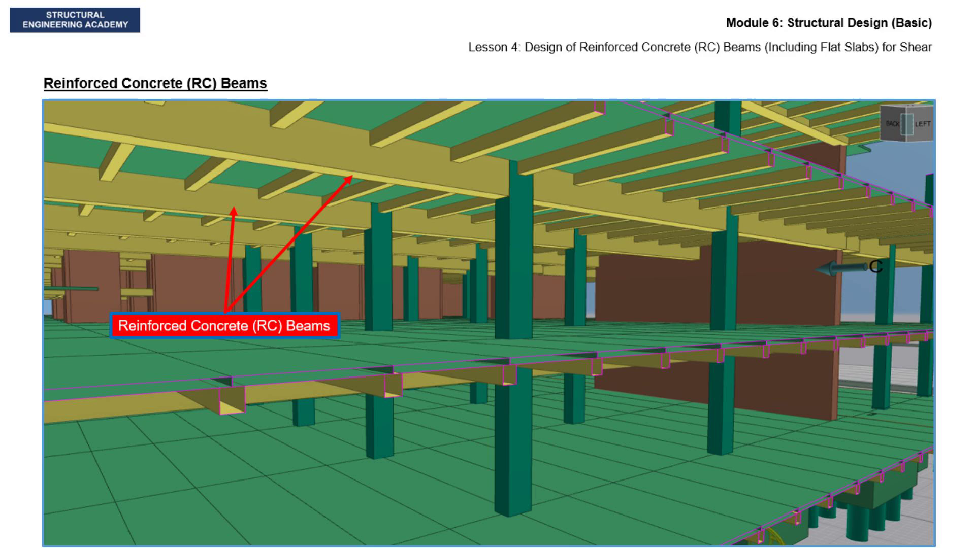
[Audio] The reinforced concrete beam is the basic structural element that make up many structural floor plates. This image shows a floor plate consisting of long span continuous beams for a real data centre project with a substantial column grid..
Scene 2 (16s)
[Audio] This is another example of a reinforced concrete beam, yet to be cast in concrete, here within a podium floor plate of a residential building complex in Kuala Lumpur..
Scene 3 (28s)
[Audio] There are three aspects to executing the reinforced concrete (RC) beam design, namely by performing the beam bending reinforcement design, the beam shear reinforcement design, and the beam deflection design check. To investigate the design of a reinforced concrete beam section with various methods, software, and codes of practice, let us establish a numerical example based on a continuous beam. Herewith is a 500 x 1000mm, 5-bay, 10m span reinforced concrete beam of grade C28/35, whereby the cylindrical compressive strength is 28MPa, and the cubic compressive strength is 35MPa. The loading tributary of the continuous beam is 5m, over which width, it carries a 200mm thick slab, which also becomes its flange. Let us say also that, the continuous beam carries a superimposed dead load (SDL) of 15kPa, and live load (LL) of 10kPa over its full 5m loading tributary width. For the purposes of this lesson, the sectional design shall be performed based on the effects on the middle interior span, as highlighted herein. In this lesson, aspect 2: shear reinforcement design, is investigated. The other aspects 1: bending reinforcement design, and 3: deflection design check, are addressed in a previous lesson..
Scene 4 (2m 10s)
[Audio] The continuous 500 x 1000mm beam, carries a uniformly distributed load, beam self-weight (SW) UDL of, 0.5m x 1.0m x 25kN/m^3 = 12.5kN/m. The continuous beam also carries a uniformly distributed load, slab self-weight (SW) UDL of, 0.2m x 25kN/m^3 x 5m tributary = 25kN/m. For additional accuracy, the beam and slab overlap could then be subtracted out as, -0.2m x 25kN/m^3 x 0.5m overlap = -2.5kN/m. And so, the actual self-weight uniformly distributed load is, 12.5 + 25 - 2.5 = 35kN/m. The continuous beam also carries a uniformly distributed load, superimposed dead load (SDL) UDL of, 15kPa x 5m tributary = 75kN/m. The total dead load G uniformly distributed load UDL, would then be 35 + 75 = 110kN/m. Finally, the continuous beam also carries a uniformly distributed load, live load (LL) UDL of, 10kPa x 5m tributary = 50kN/m. Thus, when combined and factored by 1.4G and 1.6Q, the beam carries a uniformly distributed load, ultimate limit state load (ULS) UDL of, 234kN/m. For simplicity, even though these combination factors are based on BS8110, for this lesson, we shall adopt the same combination factors, for all the other codes of practice..
Scene 5 (4m 28s)
[Audio] For the load combination case 1.4G+1.6Q, the resulting hogging bending moment for the interior span can be calculated, based on 0.079.omega 1.4G+1.6Q.L^2, resulting in a figure of 1,849 kilo Newton metre. For the load combination case 1.4G+1.6Q, the resulting sagging bending moment for the interior span can be calculated, based on 0.046.omega 1.4G+1.6Q.L^2, resulting in a figure of 1,076 kilo Newton metre..
Scene 6 (5m 13s)
[Audio] For the load combination case 1.4G+1.6Q, the resulting shear force for the interior span can be calculated, based on 0.500.omega 1.4G+1.6Q.L, resulting in a figure of 1,170kN..
Scene 7 (5m 35s)
[Audio] Finally, for the load combination case 1.0G+1.0Q, the resulting deflection for the end span can be calculated approximately as, omega G+Q, times L to the power of 4, over (154 E I), that is 160kN/m, times (10 metre) to the power of 4, over [154, times 27.0GPa, times 0.70 stiffness modifier, times 1/12, times 0.5m, times (1.0m)^3], resulting in a figure of 13mm..
Scene 8 (6m 20s)
[Audio] As well as the shear design for beams, in this lesson, we are also investigating the punching shear design of flat slabs. This is simply because, by and large, the equations are related. Thus let us investigate a representative 5 times 5 bay flat slab structure with a grid of 10m by 10m, with a slab thickness of 400mm. The columns are 800 times 800mm square in section..
Scene 9 (6m 52s)
[Audio] The superimposed dead load is 1.0kN/m^2..
Scene 10 (7m 2s)
[Audio] Finally, the live load is 5.0kN/m^2.. Slab Live Loads 5.000 kN/m2.
Scene 11 (7m 10s)
[Audio] The ULS loading pressure is thus calculated as the summation of 1.4 times the dead load pressure, and 1.6 times the live load pressure. The dead load pressure is 0.4m slab thickness, times the concrete density of 25kN/m^3, plus 1kPa. The live load pressure is 5kPa. Together, the factored summation is 23.4kPa. This ULS loading pressure acts over an area of 10m by 10m, i.e. 100m2, on each internal column, resulting in a column axial force of 2,340kN..
Scene 12 (7m 57s)
[Audio] Let us firstly investigate the shear reinforcement design of the RC beam and RC flat slab with the Hand Method..
Scene 13 (8m 5s)
[Audio] The concrete shear capacity contribution mechanisms are the uncracked concrete in the compression zone, the doweling action of the bending reinforcement and the aggregate interlock across tension cracks. The steel shear capacity contribution mechanism is the tension within the shear steel reinforcement..
Scene 14 (8m 25s)
[Audio] Once the structural analysis has been conducted, and we have the effects in terms of hogging and sagging bending moments, as well as shear forces established for the beam and flat slab, we can go ahead and design the reinforced concrete section with steel reinforcement, to effectively arrest the cracks that would otherwise propagate. Herewith, is the summary of all the primary shear capacity equations, based on the various codes of practice. We shall repeatedly return to the equations and conclusions presented herewith, after the equations within every code, have been investigated. Shown herewith are all the primary shear capacity equations, based on the British Concrete Code BS8110 Part 1..
Scene 15 (9m 33s)
[Audio] Shown herewith are all the primary shear capacity equations, based on the European Concrete Code E N 1992 Part 1-1..
Scene 16 (10m 41s)
[Audio] Shown herewith are all the primary shear capacity equations, based on the American Concrete Code ACI318 14..
Scene 17 (11m 48s)
[Audio] For the beam shear reinforcement design, based on the British Concrete Code BS8110 Part 1, we could use the 3-step equations provided in clause 3.4.5. First step, is to calculate the ultimate and design ULS shear stress, vd, which is equal to Vd over bw times d, whereby Vd is the ultimate and design ULS shear force, bw is the beam width, and d is the effective depth of the section to the centroid of the reinforcement. Subsequently, the ultimate and design ULS shear stress must be ensured to be lesser than the stipulated ultimate strength limit, calculated as 0.8 times the square root of the concrete cube strength fcu, and the absolute magnitude of 5.0Newton/mm2. Second step, is to calculate the concrete shear strength, vc, using the equation herewith as a function of the concrete cube strength fcu, and the percentage of tensile reinforcement, rho w.. The greater the concrete cube strength fcu, and/or, the percentage of tensile reinforcement, rho w, the greater the concrete shear strength, vc. Third step, is then to calculate the required area of shear steel reinforcement, Asv/S, which is equal to the beam width, bw, times the design ULS shear stress vd, minus the concrete shear strength vc, divided by 0.95fyv, where fyv is the strength or grade of the shear steel reinforcement, taken as 460Newton/mm2. The design shear capacity is correspondingly calculated as the provided area of shear steel reinforcement, Asv,prov/S, times 0.95 of the strength or grade of the shear steel reinforcement, fyv, times the effective depth, d, plus the concrete shear strength vc, times the beam width, bw, times the effective depth, d.. Ensure that the provision of area of shear steel reinforcement is at least nominal, such that it provides a nominal shear steel area capacity of more than 0.4Newton/mm2. Performing these three step calculations on the interior span shear force, Vd of 1,170kN, with a section effective depth, d of 917mm (as computed above), the ULS ultimate and design shear stress, vd would be calculated as 2.55Newton/mm2, (being lesser than the stipulated ultimate strength limit as calculated above as 4.73Newton/mm2), next, the concrete shear strength, vc, subsequently calculated as 0.79Newton/mm2, on the basis of the provision of 8 numbers of T32 longitudinal reinforcement, totalling an area of 6,434 millimetre squared, and finally the required area of shear steel reinforcement, Asv/S, would be calculated as 2.014 millimetre squared per millimetre. Correspondingly, the design shear capacity is calculated as 1,622kN, on the basis of the provision of 4 legs of T10 shear reinforcement at 100mm centres, totalling an area of 3.142 millimetre squared per millimetre..
Scene 18 (15m 34s)
[Audio] It is illustrative to investigate the shear capacity equations a little more intricately. Firstly, the concrete shear strength, vc is a function of the concrete cube strength up to C80, and the percentage of tensile reinforcement up to 3.0%. The greater the concrete cube strength fcu, and/or, the percentage of tensile reinforcement, the greater the concrete shear strength, vc. This is clearly illustrated by the graph, which shows for the chosen effective depth, d of 400mm, the increasing variation of the concrete shear strength, vc, with increasing percentage of tensile reinforcement, for various concrete cube strengths, fcu. Secondly, the concrete shear strength is independent of the effective depth beyond 400mm. This is due to the (400/d) to the fourth root term, within the concrete shear strength, vc, capacity equation. As such, the concrete shear strength variation graph need only choose the effective depth, d, of no greater than 400mm, as any greater would result in the same variation. Thirdly, for a typical C40 concrete, and for the typical effective depth of 400mm and beyond, the concrete shear strength varies from approximately, 0.5 to 1.0Newton/mm2, as the percentage of tensile reinforcement varies from 0.3% to 3.0%. Fourthly, in terms of the shear capacity components, of the ultimate and design shear strength capacity of 5.0Newton/mm2, (for a typical C40 concrete), the proportion magnitudes are made up of: a, the concrete capacity, vc between 0.5 to 1.0Newton/mm2, depending on the area of longitudinal steel provided, b, the nominal shear link capacity of 0.4Newton/mm2, and c, the design shear link capacity between 4.0 to 3.5Newton/mm2 Clearly, the greatest shear capacity component, contributing up to 90% of the design shear capacity, is provided by the design (and nominal) shear links..
Scene 19 (18m 11s)
[Audio] With the understanding that the greatest beam shear capacity component, contributing up to 90% of the design shear capacity, is provided by the design (and nominal) shear links, we could present the beam shear capacities conservatively, based on just the area of shear steel reinforcement. Thus, conservatively, the shear capacity, Vcap is calculated as just, the provided area of shear steel reinforcement, Asv,prov/S, times 0.95 of the strength or grade of the shear steel reinforcement, fyv, times the effective depth, d.. With that, the shear design for a beam could conservatively simply become, Vd, over bw times d, ensuring a magnitude lesser than 5.0Newton/mm2, followed by the shear capacity, Vcap in kilo Newton equal to Asv,prov/S in mm2/m, times 0.437, times d in metres. Examples of these steel only shear capacities, for typical shear link arrangements, are tabulated herewith for a beam depth, d in metres, or d = 1 metre. Thus to summarize, and with reference to the previous RC beam bending lesson, we could simplistically present both the bending and shear designs for a beam in similar forms, coincidentally, as follows: a, the bending design for a beam could conservatively simply be estimated as, K = M over bd^2fcu, to ensure a magnitude lesser than 0.156, followed by the moment capacity, Mcap = A s,prov times 0.33, times d, with the moment capacity, Mcap in kilo Newton metre, the provided area of longitudinal steel reinforcement, A s,prov in millimetre squared, and the effective depth, d in metres, and b, the shear design for a beam could conservatively simply be estimated as, Vd, over bw times d, ensuring a magnitude lesser than 5.0Newton/mm2, followed by the shear capacity, Vcap = Asv,prov/S, times 0.437, times d, with the shear capacity, Vcap in kilo Newton, the provided area of shear steel reinforcement, Asv,prov/S in mm2/m, and the effective depth, d in metres..
Scene 20 (20m 59s)
[Audio] For the flat slab punching shear reinforcement design, based on the British Concrete Code BS8110 Part 1, we could use the 3-step equations provided in clause 3.7.6. First step, is to calculate the ultimate ULS shear stress, which is equal to V effective,1 over u1 times d, whereby V effective,1 is the ultimate ULS shear force (note which, is additionally factored by 1.15 or 1.4, depending on whether the column is an internal column or an edge column), u1 is the column face perimeter, and d is the effective depth of the section to the centroid of the reinforcement. Subsequently, the ultimate ULS shear stress must be ensured to be lesser than the stipulated ultimate strength limit, calculated as 0.8 times the square root of the concrete cube strength fcu, and the absolute magnitude of 5.0Newton/mm2. Second step, is to calculate the concrete shear strength, vc, using the equation herewith as a function of the concrete cube strength fcu, and the percentage of tensile reinforcement, rho w.. The greater the concrete cube strength fcu, and/or, the percentage of tensile reinforcement, rho w, the greater the concrete shear strength, vc. Third step, is then to calculate the required area of shear steel reinforcement, Asv. This is evaluated depending on the level of design shear stress at the punching shear perimeter, with respect to the concrete shear strength, vc. For the case whereby the punching shear perimeter design shear stress, is lesser than 1.0 times the concrete shear strength vc, no shear links are required. For the case whereby the punching shear perimeter design shear stress, is between 1.0vc and 1.6vc, shear links are required based on the equation, Asv equals the punching shear perimeter, u, times the effective depth, d, times the design shear stress at the punching shear perimeter v, minus the concrete shear strength vc, divided by 0.95fyv, where fyv is the strength or grade of the shear steel reinforcement, taken as 460Newton/mm2. For the case whereby the punching shear perimeter design shear stress, is between 1.6vc and 2.0vc, a more onerous equation is applicable as shown herewith. Finally, for the case whereby the punching shear perimeter design shear stress, is greater than 2.0vc, design punching shear failure ensues, and the section must be resized..
Scene 21 (23m 59s)
[Audio] Performing these three step calculations on the interior column punching shear force, V of 2,340kN, with a section effective depth, d of 345mm (as computed above), the ULS ultimate and design shear stress would be calculated as 2.42, 1.03, 0.78, 0.62 and 0.51Newton/mm2, for the column face, first, second, third and fourth design punching shear perimeters, respectively. The design shear perimeter punching shear force calculation accounts for, the punching shear force area reduction, the additional factor of 1.15 or 1.4, depending on whether the column is an internal column or an edge column, and the punching shear perimeter dimensions. Step 1, the ultimate ULS shear stress at the column face, v1, must be ensured to be lesser than the stipulated ultimate strength limit, calculated as 0.8 times the square root of the concrete cube strength fcu, and the absolute magnitude of 5.0Newton/mm2, yielding a figure of 4.73Newton/mm2. Step 2, the concrete shear strength, vc, is subsequently calculated as 0.62Newton/mm2, on the basis of the provision of T20 at 150mm centres longitudinal reinforcement, totalling an area of 2,094 millimetre squared per metre, and the concrete cube strength fcu of 35Newton/mm2..
Scene 22 (26m 27s)
[Audio] Step 3, and finally, the required area of shear steel reinforcement, Asv, would be calculated as 2,828mm2, 2,972mm2, and 3,625mm2, for the first, second, and third perimeters respectively, based on the equations described..
Scene 23 (27m 57s)
[Audio] It is illustrative to investigate the punching shear capacity equations a little more intricately. Firstly, the concrete shear strength, vc is a function of the concrete cube strength up to C40, and the percentage of tensile reinforcement up to 3.0%. The greater the concrete cube strength fcu, and/or, the percentage of tensile reinforcement, the greater the concrete shear strength, vc. This is clearly illustrated by the graph, which shows for the chosen effective depth, d of 400mm, the increasing variation of the concrete shear strength, vc, with increasing percentage of tensile reinforcement, for various concrete cube strengths, fcu. Secondly, the concrete shear strength is independent of the effective depth beyond about 2,000mm. This is due to the (400/d) to the fourth root term, within the concrete shear strength, vc, capacity equation. Thirdly, for a typical C40 concrete, and for the typical effective depth of 400mm and beyond, the concrete shear strength varies from approximately, 0.5 to 1.0Newton/mm2, as the percentage of tensile reinforcement varies from 0.3% to 3.0%. Note that the lowest concrete shear strength magnitude, is 0.39Newton/mm2, for a C40 concrete and beyond. Fourthly, in terms of the shear capacity components, of the design shear strength capacity of 2.0vc in Newton/mm2, the proportion magnitudes are made up of: a, the concrete capacity, vc between 0.5 to 1.0Newton/mm2, for a typical C32/40 concrete, depending on the area of longitudinal steel provided, b, the nominal shear link capacity of 0.4Newton/mm2, and c, the design shear link capacity between 0.0 to 0.5Newton/mm2 Clearly, both the concrete and design (and nominal) shear links, could contribute to the design shear capacity in almost equal measure..
Scene 24 (30m 30s)
[Audio] The differences between the beam shear design and flat slab shear design, within the BS8110 code of practice, are thus: a, the further requirement of a 1.15 or 1.4 factor to the ultimate and design punching shear forces in the flat slab punching shear design, depending on whether the column is an internal, or an edge column, b, the absence of shear reinforcement requirement, when the shear perimeter design punching shear stress is lesser than 1.0 times the concrete shear strength, vc, c, the greater reliance on the concrete shear capacity component within the flat slab design punching shear capacity, as compared to the beam design shear capacity. The concrete shear capacity component in the flat slab design punching shear capacity, could be as high as 100%, and no lesser than 50% (proven by the fact that the shear capacity cannot be taken as any larger than 2.0vc), whilst the concrete shear capacity component within the beam design shear capacity, could be as low as 10%. It is this reliance, that subsequently requires the checking of the flat slab punching shear stress, at multiple shear perimeters in the flat slab punching shear design, starting at 1.5d from the column face, to 2.25d, to 3.0d, to 3.75d of the column face, until no further punching shear reinforcement is required, i.e. when the concrete shear capacity component is sufficient in itself, d, the further requirement of limiting the design punching shear stress at the multiple shear perimeters in the flat slab punching shear design, to 2 times the concrete shear capacity vc, instead of the stipulated ultimate strength limit, calculated as the lesser of 0.8 times the square root of the concrete cube strength fcu, and the absolute magnitude of 5.0Newton/mm2..
Scene 25 (32m 36s)
[Audio] Next, let us look into the beam shear reinforcement design based on the Eurocodes EC2. For the beam shear reinforcement design, based on the European Concrete Code E N 1992 Part 1-1, we could use the following 3-step equations deduced and derived from the principles set forth within clause 6.2. Thus now, in order to perform the beam shear reinforcement design, the first step, is to calculate the ultimate and design ULS shear stress, vd, which is equal to Vd over bw times d, whereby Vd is the ultimate and design ULS shear force, bw is the beam width, and d is the effective depth of the section to the centroid of the reinforcement. Subsequently, the ultimate and design ULS shear stress must be ensured to be lesser than the maximum shear strength, vRd,max(45) = 0.18 times, 1 minus the concrete cylinder strength fck over 250, times the concrete cylinder strength fck. Second step, is to calculate the concrete shear strength, vRd,c, using the equation herewith as a function of the concrete cylinder strength fck, the percentage of tensile reinforcement, rho w, and the axial compression or precompression, sigma cp. The greater the concrete cylinder strength fck, and/or, the percentage of tensile reinforcement, rho w, and/or the axial compression or precompression, sigma cp, the greater the concrete shear strength, vRd,c. Third step, is then to calculate the required area of shear steel reinforcement, Asv/S, which is equal to the beam width, bw, times the design ULS shear stress vd, divided by cotangent theta (which is the compression strut angle), divided by 0.78fyv, where fyv is the strength or grade of the shear steel reinforcement, taken as 500Newton/mm2. The design shear capacity is correspondingly calculated as the provided area of shear steel reinforcement, Asv,prov/S, times 0.78 of the strength or grade of the shear steel reinforcement, fyv, times the effective depth, d, times cotangent theta (which is the compression strut angle). Note that the compression strut angle, theta, could vary from 22 degrees, to 45 degrees, and is calculated based on the ratio of the actual shear stress with respect to the maximum shear strength. The design shear capacity is limited by the expression for VRd,max computed for the calculated compression strut angle theta. Finally, ensure that the provision of area of shear steel reinforcement is at least nominal, such that it provides a nominal shear steel area capacity..
Scene 26 (35m 52s)
[Audio] Performing these three step calculations on the interior span shear force, Vd of 1,170kN, with a section effective depth, d of 917mm (as computed above), the ULS ultimate and design shear stress, vd would be calculated as 2.55Newton/mm2, (being lesser than the stipulated ultimate strength limit vRd,max(45) as calculated above as 4.48Newton/mm2), next, the concrete shear strength, vRd,c, subsequently calculated as 0.60Newton/mm2, on the basis of the provision of 8 numbers of T32 longitudinal reinforcement, totalling an area of 6,434 millimetre squared, and finally the required area of shear steel reinforcement, Asv/S, would be calculated as 1.320 millimetre squared per millimetre. Correspondingly, the design shear capacity is calculated as 2,792kN, on the basis of the provision of 4 legs of T10 shear reinforcement at 100mm centres, totalling an area of 3.142 millimetre squared per millimetre, but however truncated to 1,425kN, in respect of VRd,max..
Scene 27 (37m 23s)
[Audio] It is illustrative to investigate the shear capacity equations a little more intricately. Firstly, the concrete shear strength, vRd,c is a function of the concrete cylinder strength up to C50/60, the percentage of tensile reinforcement up to 2.0%, and the axial compression or precompression at 15%. The greater the concrete cylinder strength fck, and/or, the percentage of tensile reinforcement, and/or, the axial compression or precompression, the greater the concrete shear strength, vRd,c. This is clearly illustrated by the table, which shows for the chosen effective depth, d of 400mm, the increasing variation of the concrete shear strength, vRd,c, with increasing percentage of tensile reinforcement, for various concrete cylinder strengths, fck. Secondly, the concrete shear strength is still dependent upon the effective depth beyond 400mm, as the coefficient k continues to reduce with greater effective depths. Thirdly, for a typical C32/40 concrete, and for the typical effective depth of 400mm, the concrete shear strength varies from approximately, 0.5 to 0.8Newton/mm2, as the percentage of tensile reinforcement varies from 0.3% to 2.0%. Fourthly, in terms of the shear capacity components, of the ultimate and design shear strength capacity of 5.0Newton/mm2, (for a typical C32/40 concrete), the proportion magnitudes are made up of: a, the concrete capacity, vRd,c of 0.0Newton/mm2, (i.e. no contribution), b, the nominal shear link capacity of 0.4Newton/mm2, and c, the design shear link capacity of 4.5Newton/mm2 Clearly, the exclusive shear capacity component, contributing 100% of the design shear capacity, is provided by the design (and nominal) shear links. In general, the required area of shear steel reinforcement, is lesser within the European EC2 code when compared to the British BS8110 code, this being due to the cotangent theta denominator, within the required Asv/S equation. Correspondingly, the beam concrete and steel shear capacity, is larger within the European EC2 code when compared to the British BS8110 code, this being due to the cotangent theta numerator, within the design shear capacity equation..
Scene 28 (40m 24s)
[Audio] With the understanding that the exclusive beam shear capacity component, contributing 100% of the design shear capacity, is provided by the design (and nominal) shear links, we could present the beam shear capacities conservatively, based on just the area of shear steel reinforcement. Thus, appropriately, the shear capacity, Vcap is calculated as just, the provided area of shear steel reinforcement, Asv,prov/S, times 0.78 of the strength or grade of the shear steel reinforcement, fyv, times the effective depth, d, times cotangent theta. With that, the shear design for a beam could conservatively simply become, Vd, over bw times d, ensuring a magnitude lesser than 5.0Newton/mm2, followed by the shear capacity, Vcap in kilo Newton equal to Asv,prov/S in mm2/m, times 0.965 to 0.390, for compression strut angle theta from 22 to 45 degrees respectively, times d in metres. Examples of these steel only shear capacities, for typical shear link arrangements, are tabulated herewith for a beam depth, d in metres, or d = 1 metre. Thus to summarize, and with reference to the previous RC beam bending lesson, we could simplistically present both the bending and shear designs for a beam in similar forms, coincidentally, as follows: a, the bending design for a beam could conservatively simply be estimated as, K = M over bd^2fck, to ensure a magnitude lesser than 0.167, followed by the moment capacity, Mcap = A s,prov times 0.36, times d, with the moment capacity, Mcap in kilo Newton metre, the provided area of longitudinal steel reinforcement, A s,prov in millimetre squared, and the effective depth, d in metres, and b, the shear design for a beam could conservatively simply be estimated as, Vd, over bw times d, ensuring a magnitude lesser than 5.0Newton/mm2, followed by the shear capacity, Vcap = Asv,prov/S, times 0.965 to 0.390, for compression strut angle theta from 22 to 45 degrees respectively, times d, with the shear capacity, Vcap in kilo Newton, the provided area of shear steel reinforcement, Asv,prov/S in mm2/m, and the effective depth, d in metres..
Scene 29 (43m 27s)
[Audio] We had established that the design shear capacity is limited by the expression for VRd,max computed for the calculated compression strut angle theta. Plotting a graph of the normalised strength vRd,max by the concrete cylinder strength fck, against the concrete cylinder strength fck, for various given compression strut angles theta, the shear stress magnitude above which, the design shear capacity will indeed be limited by the expression for VRd,max, can be established. Thus, the optimum shear design would be to limit the shear stress to that consistent with the compression strut angle being 22 degrees for the chosen concrete grade, in order to minimise the shear link requirements..
Scene 30 (44m 41s)
[Audio] For the flat slab punching shear reinforcement design, based on the European Concrete Code E N 1992 Part 1-1, we could use the 3-step equations provided in clause 6.4. First step, is to calculate the ultimate ULS shear stress, which is equal to V effective,1 over u1 times d, whereby V effective,1 is the ultimate ULS shear force (note which, is additionally factored by 1.15, 1.4, or 1.5, depending on whether the column is an internal column, an edge column, or a corner column), u1 is the column face perimeter, and d is the effective depth of the section to the centroid of the reinforcement. Subsequently, the ultimate ULS shear stress must be ensured to be lesser than the maximum shear strength, vRd,max = 0.20 times, 1 minus the concrete cylinder strength fck over 250, times the concrete cylinder strength fck as given by clause 6.2.2(6). Second step, is to calculate the concrete shear strength, vRd,c, using the equation herewith as a function of the concrete cylinder strength fck, the percentage of tensile reinforcement, rho w, and the axial compression or precompression, sigma cp. The greater the concrete cylinder strength fck, and/or, the percentage of tensile reinforcement, rho w, and/or the axial compression or precompression, sigma cp, the greater the concrete shear strength, vRd,c. Third step, is then to calculate the required area of shear steel reinforcement, Asv. This is evaluated depending on the level of design shear stress at the punching shear perimeter, with respect to the concrete shear strength, vRd,c. For the case whereby the punching shear perimeter design shear stress, is lesser than 1.0 times the concrete shear strength vRd,c, no shear links are required. For the case whereby the punching shear perimeter design shear stress, is between 1.0vRd,c and a nominal shear strength capacity based on 75% of vRd,c, plus a nominal shear links requirement as shown, shear links are required based on the equation, Asv equals punching shear perimeter, u, times the shear link spacing, sv, times 3 or 2, times 0.08, divided by gamma s, times the square root of the concrete cylinder strength fck, divided by 1.5fywd,ef, where fywd,ef is as shown. For the case whereby the punching shear perimeter design shear stress, is between the nominal shear strength capacity and 2.0vRd,c, Asv equals the punching shear perimeter, u, times the shear link spacing, sv, times 3 or 2, times the design shear stress at the punching shear perimeter v, minus 75% of the concrete shear strength vRd,c, divided by 1.5fywd,ef, where fywd,ef is as shown. Finally, for the case whereby the punching shear perimeter design shear stress, is greater than 2.0vRd,c, design punching shear failure ensues, and the section must be resized..
Scene 31 (48m 36s)
[Audio] Performing these three step calculations on the interior column punching shear force, V of 2,340kN, with a section effective depth, d of 345mm (as computed above), the ULS ultimate and design shear stress would be calculated as 2.42, 1.03, 0.72, 0.55 and 0.45Newton/mm2, for the column face, first, second, third and fourth design punching shear perimeters, respectively. The design shear perimeter punching shear force calculation accounts for, the additional factor of 1.15, 1.4, or 1.5, depending on whether the column is an internal column, an edge column, or a corner column, and the punching shear perimeter dimensions. In this code, the punching shear force area reduction, is not accounted for. Step 1, the ultimate ULS shear stress at the column face, v1, must be ensured to be lesser than the maximum shear strength, vRd,max = 0.20 times, 1 minus the concrete cylinder strength fck of 28Newton/mm2 over 250, times the concrete cylinder strength fck of 28Newton/mm2, yielding a figure of 4.97Newton/mm2. Step 2, the concrete shear strength, vRd,c, is subsequently calculated as 0.54Newton/mm2, on the basis of the provision of T20 at 150mm centres longitudinal reinforcement, totalling an area of 2,094 millimetre squared per metre, and the concrete cylinder strength fck of 28Newton/mm2..
Scene 32 (51m 1s)
[Audio] Step 3, and finally, the required area of shear steel reinforcement, Asv, would be calculated as 4,174mm2, 2,362mm2, and 3,074mm2, for the first, second, and third perimeters respectively, based on the equations described..
Scene 33 (52m 51s)
[Audio] It is illustrative to investigate the punching shear capacity equations a little more intricately. Firstly, the concrete shear strength, vRd,c is a function of the concrete cylinder strength up to C50/60, the percentage of tensile reinforcement up to 2.0%, and the axial compression or precompression at 15%. The greater the concrete cylinder strength fck, and/or, the percentage of tensile reinforcement, and/or, the axial compression or precompression, the greater the concrete shear strength, vRd,c. This is clearly illustrated by the table, which shows for the chosen effective depth, d of 400mm, the increasing variation of the concrete shear strength, vRd,c, with increasing percentage of tensile reinforcement, for various concrete cylinder strengths, fck. Secondly, the concrete shear strength is still dependent upon the effective depth beyond 400mm, as the coefficient k continues to reduce with greater effective depths. Thirdly, for a typical C32/40 concrete, and for the typical effective depth of 400mm, the concrete shear strength varies from approximately, 0.5 to 0.8Newton/mm2, as the percentage of tensile reinforcement varies from 0.3% to 2.0%. Note that the lowest concrete shear strength magnitude, is 0.44Newton/mm2, for a C32/40 concrete. Fourthly, in terms of the shear capacity components, of the design shear strength capacity of 2.0vRd,c in Newton/mm2, the proportion magnitudes are made up of: a, the concrete capacity, vRd,c between 0.5 to 0.8Newton/mm2, for a typical C32/40 concrete, depending on the area of longitudinal steel provided, b, the nominal shear link capacity of 0.4Newton/mm2, and c, the design shear link capacity between 0.0 to 0.4Newton/mm2 Clearly, both the concrete and design (and nominal) shear links, could contribute to the design shear capacity in almost equal measure. In general, the slab concrete shear capacity, is lesser within the European EC2 code when compared to the British BS8110 code..
Scene 34 (55m 42s)
[Audio] The differences between the beam shear design and flat slab shear design, within the EC2 code of practice, are thus: a, the further requirement of a 1.15, 1.4, or 1.5 factor to the ultimate and design punching shear forces in the flat slab punching shear design, depending on whether the column is an internal, an edge, or a corner column, b, the absence of shear reinforcement requirement, when the shear perimeter design punching shear stress is lesser than 1.0 times the concrete shear strength, vRd,c, c, the greater reliance on the concrete shear capacity component within the flat slab design punching shear capacity, as compared to the beam design shear capacity. The concrete shear capacity component in the flat slab design punching shear capacity, could be as high as 100%, and no lesser than 50% (proven by the fact that the shear capacity cannot be taken as any larger than 2.0vRd,c), whilst the concrete shear capacity component within the beam design shear capacity, could be as low as 0%. It is this reliance, that subsequently requires the checking of the flat slab punching shear stress, at multiple shear perimeters in the flat slab punching shear design, starting at 2.0d from the column face, to 3.5d, to 5.0d, to 6.5d of the column face, until no further punching shear reinforcement is required, i.e. when the concrete shear capacity component is sufficient in itself, d, the further requirement of limiting the design punching shear stress at the multiple shear perimeters in the flat slab punching shear design, to 2 times the concrete shear capacity vRd,c, instead of lesser than the maximum shear strength, vRd,max = 0.20 times, 1 minus the concrete cylinder strength fck over 250, times the concrete cylinder strength fck as given by clause 6.2.2(6)..
Scene 35 (57m 59s)
[Audio] Next, let us look into the beam shear reinforcement design based on the American ACI318 14. For the beam shear reinforcement design, based on the American Concrete Code ACI318 14, we could use the following 3-step equations deduced and derived from the principles set forth within clause 22.5. Thus now, in order to perform the beam shear reinforcement design, the first step, is to calculate the ultimate and design ULS shear stress, vd, which is equal to Vd* over bw times d, whereby Vd* is the ultimate and design ULS shear force, bw is the beam width, and d is the effective depth of the section to the centroid of the reinforcement. Subsequently, the ultimate and design ULS shear stress must be ensured to be lesser than the stipulated ultimate strength limit, calculated as the strength reduction factor for shear, phi, of 0.75, times 0.83, times the square root of the concrete cylinder strength fc'. Second step, is to calculate the concrete shear strength, vc, using the equation herewith as a function of the concrete cylinder strength fc'. The concrete shear strength, vc is calculated as, the strength reduction factor for shear, phi, of 0.75, times 0.17, times the square root of the concrete cylinder strength fc'. The greater the concrete cylinder strength fc', the greater the concrete shear strength, vc. Third step, is then to calculate the required area of shear steel reinforcement, Asv/S, which is equal to the beam width, bw, times the design ULS shear stress vd, minus the concrete shear strength vc, divided by the strength reduction factor for shear, phi, divided by fyv, where fyv is the strength or grade of the shear steel reinforcement, limited to 420Newton/mm2. The design shear capacity is correspondingly calculated as the strength reduction factor for shear, phi, times the provided area of shear steel reinforcement, Asv,prov/S, times the strength or grade of the shear steel reinforcement, fyv, times the effective depth, d.. Performing these three step calculations on the interior span shear force, Vd* of 1,170kN, with a section effective depth, d of 917mm (as computed above), the ULS ultimate and design shear stress, vd would be calculated as 2.55Newton/mm2, (being lesser than the stipulated ultimate strength limit as calculated above as 3.29Newton/mm2), next, the concrete shear strength, vc, subsequently calculated as 0.67Newton/mm2, and finally the required area of shear steel reinforcement, Asv/S, would be calculated as 2.980 millimetre squared per millimetre. Correspondingly, the design shear capacity is calculated as 1,217kN, on the basis of the provision of 4 legs of T10 shear reinforcement at 100mm centres, totalling an area of 3.142 millimetre squared per millimetre..
Scene 36 (1h 1m 47s)
[Audio] It is illustrative to investigate the shear capacity equations a little more intricately. Firstly, the concrete shear strength, vc is a function of the concrete cylinder strength up to C70/85. The greater the concrete cylinder strength fc', the greater the concrete shear strength, vc. Secondly, the concrete shear strength is independent of the effective depth. Thirdly, for a typical C32/40 concrete, the concrete shear strength is approximately, 0.7Newton/mm2. Fourthly, in terms of the shear capacity components, of the ultimate and design shear strength capacity of 3.5Newton/mm2, (for a typical C32/40 concrete), the proportion magnitudes are made up of: a, the concrete capacity, vc of approximately 0.7Newton/mm2, b, the nominal shear link capacity of 0.35Newton/mm2, and c, the design shear link capacity of 2.5Newton/mm2 Clearly, the greatest shear capacity component, contributing 80% of the design shear capacity, is provided by the design (and nominal) shear links. In general, the required area of shear steel reinforcement, is greater within the American ACI318 code when compared to the British BS8110 code, this being due to the strength reduction factor for shear, phi, denominator, within the required Asv/S equation. Correspondingly, the beam concrete and steel shear capacity, is lesser within the American ACI318 code when compared to the British BS8110 code, this being due to the strength reduction factor for shear, phi, numerator, within the design shear capacity equation..
Scene 37 (1h 3m 57s)
[Audio] With the understanding that the greatest beam shear capacity component, contributing 80% of the design shear capacity, is provided by the design (and nominal) shear links, we could present the beam shear capacities conservatively, based on just the area of shear steel reinforcement. Thus, conservatively, the shear capacity, Vcap is calculated as just, the provided area of shear steel reinforcement, Asv,prov/S, times 0.75 of the strength or grade of the shear steel reinforcement, fyv, times the effective depth, d.. With that, the shear design for a beam could conservatively simply become, Vd*, over bw times d, ensuring a magnitude lesser than 3.5Newton/mm2, followed by the shear capacity, Vcap in kilo Newton equal to Asv,prov/S in mm2/m, times 0.315, times d in metres. Examples of these steel only shear capacities, for typical shear link arrangements, are tabulated herewith for a beam depth, d in metres, or d = 1 metre. Thus to summarize, and with reference to the previous RC beam bending lesson, we could simplistically present both the bending and shear designs for a beam in similar forms, coincidentally, as follows: a, the bending design for a beam could conservatively simply be estimated as, K = M over bd^2fcu, to ensure a magnitude lesser than 0.156, followed by the moment capacity, Mcap = A s,prov times 0.33, times d, with the moment capacity, Mcap in kilo Newton metre, the provided area of longitudinal steel reinforcement, A s,prov in millimetre squared, and the effective depth, d in metres, and b, the shear design for a beam could conservatively simply be estimated as, Vd*, over bw times d, ensuring a magnitude lesser than 3.5Newton/mm2, followed by the shear capacity, Vcap = Asv,prov/S, times 0.315, times d, with the shear capacity, Vcap in kilo Newton, the provided area of shear steel reinforcement, Asv,prov/S in mm2/m, and the effective depth, d in metres..
Scene 38 (1h 6m 46s)
[Audio] For the flat slab punching shear reinforcement design, based on the American Concrete Code ACI318 14, we could use the 3-step equations provided in clause 22.6. First step, is to calculate the ultimate ULS shear stress, which is equal to V effective,1 over u2 times d, whereby V effective,1 is the ultimate ULS shear force (note which, is additionally factored by 1.15 or 1.4, depending on whether the column is an internal column or an edge column), u1 is the column face perimeter, u2 is the first shear perimeter, and d is the effective depth of the section to the centroid of the reinforcement. Note for ACI318, the column face punching shear perimeter, u1 is taken as first shear perimeter (i.e. critical shear perimeter), u2 as per clause 22.6.4.1. Subsequently, the ultimate ULS shear stress must be ensured to be lesser than the stipulated ultimate strength limit, calculated as the strength reduction factor for shear, phi, of 0.75, times 0.5, times the square root of the concrete cylinder strength fc'. Second step, is to calculate the concrete shear strength, vc, using the equations herewith as a function of the concrete cylinder strength fc'. The greater the concrete cylinder strength fc', the greater the concrete shear strength, vc. Table 22.6.5.2 is first used to check the shear strength at the first shear perimeter, however in the case that shear links are required, table 22.6.6.1 would have to be used to ascertain the concrete shear strength at subsequent perimeters. Third step, is then to calculate the required area of shear steel reinforcement, Asv. This is evaluated depending on the level of design shear stress at the punching shear perimeter, with respect to the concrete shear strength, vc. For the case whereby the punching shear perimeter design shear stress, is lesser than 1.0 times phi, times the concrete shear strength vc, no shear links are required. For the case whereby the punching shear perimeter design shear stress, is between 1.0 times phi, times vc, and the nominal shear capacity based on phi, times 0.17, times the square root of the concrete cylinder strength of fc', plus a nominal shear links requirement as shown, shear links are required based on the equation, Asv equals 4, times the nominal shear strength capacity, times the punching shear perimeter, u, times the shear link spacing, sv, divided by fyv, where fyv is the strength or grade of the shear steel reinforcement, taken to a maximum of 420Newton/mm2. For the case whereby the punching shear perimeter design shear stress, is more than the nominal shear capacity based on phi, times 0.17, times the square root of the concrete cylinder strength of fc', plus a nominal shear links requirement as shown, shear links are required based on the equation, Asv equals 4, times the design shear stress at the punching shear perimeter v, minus phi, times 0.17, times the square root of the concrete cylinder strength of fc', times the punching shear perimeter, u, times the shear link spacing, sv, divided by phi, times fyv, where fyv is the strength or grade of the shear steel reinforcement, taken to a maximum of 420Newton/mm2. Finally, for the case whereby the punching shear perimeter design shear stress, is greater than the strength reduction factor for shear, phi, times 0.5, times the square root of the concrete cylinder strength of fc', design punching shear failure ensues, and the section must be resized..
Scene 39 (1h 11m 12s)
[Audio] Performing these three step calculations on the interior column punching shear force, V of 2,340kN, with a section effective depth, d of 345mm (as computed above), the ULS ultimate and design shear stress would be calculated as 1.69, 1.68, 1.24, 0.82 and 0.59Newton/mm2, for the column face, first, second, third and fourth design punching shear perimeters, respectively. The design shear perimeter punching shear force calculation accounts for, the punching shear force area reduction, the additional factor of 1.15 or 1.4, depending on whether the column is an internal column or an edge column, and the punching shear perimeter dimensions. Step 1, the ultimate ULS shear stress at the column face, v1, must be ensured to be lesser than the stipulated ultimate strength limit, calculated as the strength reduction factor for shear, phi, of 0.75, times 0.5, times the square root of the concrete cylinder strength fc', yielding a figure of 1.98Newton/mm2. Step 2, the concrete shear strength, phi times vc, is subsequently calculated as 1.31, 0.67, 0.67 and 0.67Newton/mm2, for the first, second, third and fourth design punching shear perimeters, respectively, on the basis of the concrete cylinder strength fc' of 28Newton/mm2..
Scene 40 (1h 13m 50s)
[Audio] Step 3, and finally, the required area of shear steel reinforcement, Asv, would be calculated as 8,777mm2, 6,637 mm2, and 4,527mm2, for the first, second, and third perimeters respectively, based on the equations described. Other perimeters do not require design shear links, due to the fact that punching shear perimeter design shear stress, is lesser than 1.0 times phi, times the concrete shear strength vc..
Scene 41 (1h 15m 19s)
[Audio] It is illustrative to investigate the punching shear capacity equations a little more intricately. Firstly, the concrete shear strength, phi times vc, is a function of the concrete cylinder strength up to C70/85. The greater the concrete cylinder strength fc', the greater the concrete shear strength, phi times vc. Secondly, the concrete shear strength is still dependent upon the effective depth, with greater shear strengths achieved with greater effective depths. Thirdly, for a typical C32/40 concrete, the concrete shear strength could be approximately, 1.4Newton/mm2, based on the equation phi times 0.33, times the square root of the concrete cylinder strength fc'. Fourthly, in terms of the shear capacity components, of the design shear strength capacity of phi times 0.5, times the square root of the concrete cylinder strength fc' in Newton/mm2, the proportion magnitudes are made up of: a, the concrete capacity, phi times vc of 0.7Newton/mm2 based on phi times 0.17, times the square root of the concrete cylinder strength fc', for a typical C32/40 concrete, noting that the concrete capacity component is reduced from 0.33 to 0.17 when the steel capacity component is also mobilized, b, the nominal shear link capacity of 0.26Newton/mm2, and c, the design shear link capacity of 1.1Newton/mm2 Clearly, both the concrete and design (and nominal) shear links, could contribute to the design shear capacity in almost equal measure. In general, the slab concrete shear capacity, is greater within the American ACI318 code when compared to the British BS8110 code..
Scene 42 (1h 17m 32s)
[Audio] The differences between the beam shear design and flat slab shear design, within the ACI318 code of practice, are thus: a, the further requirement of a 1.15 or 1.4 factor to the ultimate and design punching shear forces in the flat slab punching shear design, depending on whether the column is an internal, or an edge column, b, the absence of shear reinforcement requirement, when the shear perimeter design punching shear stress is lesser than 1.0, times the concrete shear strength phi, times vc, c, the greater reliance on the concrete shear capacity component within the flat slab design punching shear capacity, as compared to the beam design shear capacity. The concrete shear capacity component in the flat slab design punching shear capacity, could be as high as 100%, and generally no lesser than 35%, whilst the concrete shear capacity component within the beam design shear capacity, could be as low as 20%. It is this reliance, that subsequently requires the checking of the flat slab punching shear stress, at multiple shear perimeters in the flat slab punching shear design, starting at 0.5d from the column face, to 1.5d, to 3.0d, to 4.5d of the column face, until no further punching shear reinforcement is required, i.e. when the concrete shear capacity component is sufficient in itself, d, the further requirement of limiting the design punching shear stress at the multiple shear perimeters in the flat slab punching shear design, to phi, times 0.5, times the square root of the concrete cylinder strength fc', instead of the stipulated ultimate strength limit, calculated as phi, times 0.83, times the square root of the concrete cylinder strength fc'..
Scene 43 (1h 19m 36s)
[Audio] Now, finally, let us tabulate the concrete shear strengths we have calculated for beam and flat slabs, with respect to the concrete grade. Also, for a full picture, let us make comparison of these concrete shear strengths to other strengths, such as to bending and axial strengths, for not only reinforced concrete sections, but also post-tensioned concrete, and structural steel sections. In reinforced concrete sections undergoing bending, we saw that the extreme fibre tensile stress reaches more or less 93.6% of its concrete grade, at the practical limit. If we look at structural steel sections undergoing bending, again we see the same thing, i.e. that the extreme fibre tensile stress reaches more or less 100% of its steel grade, at the ultimate limit state. But when we look at post-tensioned (PT) concrete, it is quite different, in that, unlike reinforced concrete, whereby the section bends and cracks, and reinforcement is provided to arrest the cracks, here in post-tensioned (PT) concrete, tendon forces are applied to negate the externally applied loads, and thus maintain the concrete section in compression as much and as far as possible. In doing so, the post-tensioned (PT) concrete, would then be stressed to around, only 5-10% of its concrete grade, at its extreme fibre. Next, when we look at concrete sections undergoing axial compression, the average compressive stress limit is 45 to 55% of the concrete grade. For structural steel sections undergoing axial compression (or axial tension for that matter), the average compressive or tensile stress limit is 100% of the steel grade, at the ultimate limit state..
Scene 44 (1h 21m 35s)
[Audio] Finally, for reinforced concrete sections undergoing shear without shear links, the average shear stress limit is 1.25 to 2.5% of its concrete grade for beams, and, 1.25 to 3.5% of its concrete grade for flat slabs. For reinforced concrete sections undergoing shear with shear links, the average shear stress limit is 8.75 to 12.5% of its concrete grade for beams, and, 2.5 to 5.0% of its concrete grade for flat slabs. In comparison, for structural steel sections undergoing shear, the average shear stress limit is 60% of the steel grade, at the ultimate limit state..
Scene 45 (1h 22m 41s)
[Audio] The stress levels could also be illustrated pictorially as shown herewith, presented on a graph of 0%fcu to 100%fcu. Again, in reinforced concrete sections undergoing bending, we saw that the extreme fibre tensile stress reaches more or less 93.6% of its concrete grade, at the practical limit. If we look at structural steel sections undergoing bending, again we see the same thing, i.e. that the extreme fibre tensile stress reaches more or less 100% of its steel grade, at the ultimate limit state. The post-tensioned (PT) concrete, would be stressed to around, only 5-10% of its concrete grade, at its extreme fibre. Next, when we look at concrete sections undergoing axial compression, the average compressive stress limit is 45 to 55% of the concrete grade. For structural steel sections undergoing axial compression (or axial tension for that matter), the average compressive or tensile stress limit is 100% of the steel grade, at the ultimate limit state. For structural steel sections undergoing shear, the average shear stress limit is 60% of the steel grade, at the ultimate limit state..
Scene 46 (1h 24m 6s)
[Audio] Now zooming into the 10% stress level chart as shown herewith, presented on a graph of 0%fcu to 10%fcu, we could illustrate the concrete shear strength limits. Again, for reinforced concrete sections undergoing shear without shear links, the average shear stress limit is 2.0 to 3.5% of its concrete grade for flat slabs. For reinforced concrete sections undergoing shear with shear links, the average shear stress limit is 8.75 to 12.5% of its concrete grade for beams, and, 4.0 to 5.0% of its concrete grade for flat slabs..
Scene 47 (1h 25m 24s)
[Audio] Let us now establish some major conclusions from the aforementioned reinforced concrete beam and flat slab shear reinforcement design. First, the beam concrete and steel shear capacity, is least within the American Concrete Code ACI318 14, followed by the British Concrete Code BS8110 Part 1, and finally the European Concrete Code EN 1992 Part 1-1. A generally conservative beam shear reinforcement design could be performed to ACI318, BS8110, and to EN 1992 Part 1-1, by only considering the shear steel contribution to the shear capacity, resulting in the following equations for a C32/40 concrete beam: a, to the ACI318, in terms of shear capacity, the shear design for a beam could conservatively simply be estimated as, Vd*, over bw times d, ensuring a magnitude lesser than 3.5Newton/mm2, followed by the shear capacity, Vcap = Asv,prov/S, times 0.315, times d, with the shear capacity, Vcap in kilo Newton, the provided area of shear steel reinforcement, Asv,prov/S in mm2/m, and the effective depth, d in metres, b, to the BS8110, in terms of shear capacity, the shear design for a beam could conservatively simply be estimated as, Vd, over bw times d, ensuring a magnitude lesser than 5.0Newton/mm2, followed by the shear capacity, Vcap = Asv,prov/S, times 0.437, times d, with the shear capacity, Vcap in kilo Newton, the provided area of shear steel reinforcement, Asv,prov/S in mm2/m, and the effective depth, d in metres, and c, to the EC2, in terms of shear capacity, the shear design for a beam could conservatively simply be estimated as, Vd, over bw times d, ensuring a magnitude lesser than 5.0Newton/mm2, followed by the shear capacity, Vcap = Asv,prov/S, times 0.965 to 0.390, for compression strut angle theta from 22 to 45 degrees respectively, times d, with the shear capacity, Vcap in kilo Newton, the provided area of shear steel reinforcement, Asv,prov/S in mm2/m, and the effective depth, d in metres..
Scene 48 (1h 28m 27s)
[Audio] Second, based on the aforementioned equations, the practical limit to the ultimate average shear stress of a reinforced concrete beam section (of typical C32/40 concrete), a, to the ACI318, the ultimate average shear stress limit of 3.5Newton/mm2, b, to the BS8110, the ultimate average shear stress limit of 5.0Newton/mm2, and c, to the EC2, the ultimate average shear stress limit of 5.0Newton/mm2. These work out to be around 8.75% to 12.5% of its concrete grade, i.e. the concrete characteristic cube strength, fcu. This limit also applies to the ultimate average punching shear stress at the column face of the flat slab..
Scene 49 (1h 29m 26s)
[Audio] Third, the slab concrete shear capacity at the punching shear perimeters, is least within the European Concrete Code EN 1992 Part 1-1, followed by the British Concrete Code BS8110 Part 1, and finally the American Concrete Code ACI318 14. A slab shear reinforcement design at the punching shear perimeters could be performed to EN 1992 Part 1-1, BS8110 and to ACI318, by considering both the concrete and shear steel contribution to the shear capacity, resulting in the following equations for a C32/40 concrete slab: a, to the EC2, the punching shear perimeter design shear strength capacity of 2.0vRd,c, or 1.0 to 1.6Newton/mm2, depending on the area of longitudinal steel provided, b, to the BS8110, the punching shear perimeter design shear strength capacity of 2.0vc, or 1.0 to 2.0Newton/mm2, depending on the area of longitudinal steel provided, and c, to the ACI318, the punching shear perimeter design shear strength capacity of the strength reduction factor for shear, phi, of 0.75, times 0.5, times the square root of the concrete cylinder strength fc', or 2.12Newton/mm2..
Scene 50 (1h 31m 4s)
[Audio] Fourth, based on the aforementioned equations, the practical limit to the ultimate average shear stress of a reinforced concrete slab section (of typical C32/40 concrete) at the punching shear perimeters, a, to the EC2, the punching shear perimeter ultimate average shear stress limit of 1.6Newton/mm2, b, to the BS8110, the punching shear perimeter ultimate average shear stress limit of 2.0Newton/mm2, and c, to the ACI318, the punching shear perimeter ultimate average shear stress limit of 2.12Newton/mm2. These work out to be around 4.0% to 5.0% of its concrete grade, i.e. the concrete characteristic cube strength, fcu..