Scene 1 (0s)
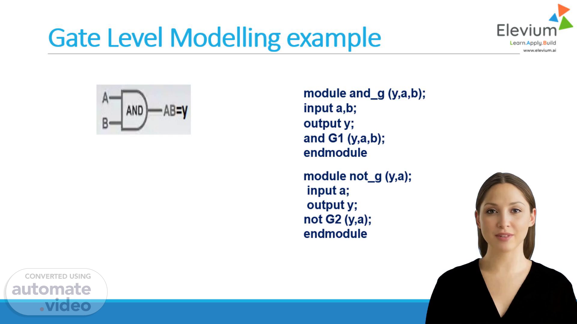
[Virtual Presenter] Welcome to this training video. We will explore the basics of gate level modelling through an example. This module, and_g, represents a logical AND operation, while G1 is the actual gate performing the operation. We will examine the properties of this gate and how it can be used to create more complex circuits. Let's begin our analysis. Last updated on June 10, 2023 The content of this video is for informational purposes only. No warranties, express or implied, are made regarding the accuracy or reliability of the content. We do not warrant or represent that the use of the content will result in any particular outcome or benefit. In no event will we be liable for any direct, indirect, incidental, special, punitive, consequential or other damages whatsoever, arising out of or connected with the use of the content. You are responsible for your own use of the content, and for your own benefit or lack thereof. By using the content, you agree to these terms. If you disagree with any of these terms, you must leave the site immediately. Your continued use of the site following the posting of any changes to these terms constitutes acceptance of those changes. We reserve the right, at our sole discretion, to modify or replace any part of these terms at any time. It is your responsibility to check our site periodically for any changes to these terms. These terms shall be governed by and construed in accordance with the laws of the State of California, without giving effect to any principles of conflicts of law. Any dispute arising out of or related to these terms shall be resolved exclusively by the State courts located in Santa Clara County, California. We are not responsible for any third-party content that may be accessed through our site. We do not endorse, recommend, or guarantee any third-party content that may be accessed through our site. Your use of the site is subject to our Privacy Policy. Please review our Privacy Policy for more information. We reserve the right to change our Privacy Policy at any time. We are not responsible for any third-party content that may be accessed through our site. We do not endorse, recommend, or guarantee any third-party content that may be accessed through our site. Your use of the site is subject to our Privacy Policy. Please review our Privacy Policy for more information. We reserve the right to change our Privacy Policy at any time. We are not responsible for any third-party content that may be accessed through our site. We do not endorse, recommend, or guarantee any third-party content that may be accessed through our site. Your use of the site is subject to our Privacy Policy. Please review our Privacy Policy for more information. We reserve the right to change our Privacy Policy at any time. We are not responsible for any third-party content that may be accessed through our site. We do not endorse, recommend, or guarantee any third-party content that may be accessed through our site. Your use of the site is subject to our Privacy Policy. Please review our Privacy Policy for more information. We reserve the right to change our Privacy Policy at any time. We are not responsible for any third-party content that may be accessed through our site. We do not endorse, recommend, or guarantee any third-party content that may be accessed through our site. Your use of the site is subject to our Privacy Policy. Please review our Privacy Policy for more information. We reserve the right to change our Privacy Policy at any time. We are not responsible for any third-party content that may be accessed through our site. We do not endorse, recommend, or guarantee any third-party content that may be accessed through our site. Your use of the site is subject to our Privacy Policy. Please review our Privacy Policy for more information. We reserve the right to change our Privacy Policy at any time. We are not responsible for any third-party content that may be accessed through our site. We do not endorse, recommend, or guarantee any third-party content that may be accessed through our site. Your use of the site is subject to our Privacy Policy. Please review our Privacy Policy for more information. We reserve the right to change our Privacy Policy at any time. We are not responsible for any third-party content that may be accessed through our site. We do not endorse, recommend, or guarantee any third-party content that may be accessed through our site. Your use of the site is subject to our Privacy Policy. Please review our Privacy Policy for more information. We reserve the right to change our Privacy Policy at any time. We are not responsible for any third-party content that may be accessed through our site. We do not endorse, recommend, or guarantee any third-party content that may be accessed through our site. Your use of the site is subject to our Privacy Policy. Please review our Privacy Policy for more information. We reserve the.
Scene 2 (4m 59s)
[Audio] The VHDL language provides a set of built-in primitives that can be used to model digital circuits. These primitives include AND, OR, NAND, NOR, XNOR, and XOR gates. The VHDL language also includes a set of operators that can be used to combine these gates into more complex logic functions. The VHDL language supports both gate-level and structural modelling. Gate-level modelling involves looking at the individual gates and their interactions, while structural modelling looks at how these gates are connected together to form larger digital circuits. Structural modelling is often used when designing large digital systems, as it allows designers to focus on the overall system architecture and make decisions about how components should be connected. Structural modelling can also help identify potential problems early on, such as conflicts between different components or limitations in component performance. By combining the insights gained from gate-level and structural modelling, designers can create more efficient and effective digital systems..
Scene 3 (6m 13s)
[Audio] The half adder is a digital circuit that adds two binary numbers. It has three inputs: two bits to be added, and a carry-in bit. The half adder produces four outputs: the sum and the carry-out. The sum is the result of adding the two input bits, while the carry-out is the result of adding the carry-in bit to the sum of the two input bits. To build the half adder, we need to connect the inputs to the outputs through a series of logic gates. The first step is to build the XOR gate, which takes two inputs and produces an output based on whether the inputs are different. The next step is to build the AND gate, which takes two inputs and produces an output based on whether both inputs are true. We can use the XOR gate to build the carry-out bit, and the AND gate to build the sum bit. We can also use a multiplexer to select which of two inputs to use for the output. The final step is to connect the outputs of the XOR and AND gates to form the half adder. By using structural modelling, we can easily create and modify digital circuits, and then simulate their behavior to see how they respond to different inputs..
Scene 4 (7m 28s)
[Audio] We will use built-in primitives to develop structural models. Built-in primitives are provided by the tool and can be used at the gate-level. They are pre-defined and can be used as is. They are useful for creating digital circuits. They can be used to create complex digital circuits. We can use them to create modules that can be instantiated in our design. We can use them to create digital circuits with multiple inputs and outputs. We can use them to create digital circuits with different logic functions. We can use them to create digital circuits with different gate types. We can use them to create digital circuits with different clocking schemes. We can use them to create digital circuits with different reset schemes. We can use them to create digital circuits with different power management schemes. We can use them to create digital circuits with different memory elements. We can use them to create digital circuits with different control signals. We can use them to create digital circuits with different status signals. We can use them to create digital circuits with different data signals. We can use them to create digital circuits with different address signals. We can use them to create digital circuits with different data transfer signals. We can use them to create digital circuits with different interrupt signals. We can use them to create digital circuits with different exception signals. We can use them to create digital circuits with different clock signals. We can use them to create digital circuits with different reset signals. We can use them to create digital circuits with different enable signals. We can use them to create digital circuits with different clock enable signals. We can use them to create digital circuits with different synchronous signals. We can use them to create digital circuits with different asynchronous signals. We can use them to create digital circuits with different combinational logic. We can use them to create digital circuits with different sequential logic. We can use them to create digital circuits with different arithmetic logic. We can use them to create digital circuits with different control logic. We can use them to create digital circuits with different status logic. We can use them to create digital circuits with different data logic. We can use them to create digital circuits with different address logic. We can use them to create digital circuits with different data transfer logic. We can use them to create digital circuits with different interrupt logic. We can use them to create digital circuits with different exception logic. We can use them to create digital circuits with different clock logic. We can use them to create digital circuits with different reset logic. We can use them to create digital circuits with different enable logic. We can use them to create digital circuits with different clock enable logic. We can use them to create digital circuits with different synchronous logic. We can use them to create digital circuits with different asynchronous logic. We can use them to create digital circuits with different combinational logic. We can use them to create digital circuits with different sequential logic. We can use them to create digital circuits with different arithmetic logic. We can use them to create digital circuits with different control logic. We can use them to create digital circuits with different status logic. We can use them to create digital circuits with different data logic. We can use them to create digital circuits with different address logic. We can use them to create digital circuits with different data transfer logic. We can use.
Scene 5 (11m 12s)
[Audio] The gate level model describes the individual gates used to implement a digital logic function. This model focuses on the gates themselves rather than the overall structure of the circuit. For example, a half adder is typically implemented using three AND gates, one OR gate, and one NOT gate. The gate level model also includes other types of gates such as XOR gates. These gates are used to perform specific logical operations. The gate level model provides a detailed view of the individual gates used to implement a digital logic function. It helps designers to understand how the gates are connected together to form the final circuit. The gate level model is useful for designing and testing digital circuits because it allows designers to analyze the behavior of individual gates and how they interact with each other..
Scene 6 (12m 6s)
[Audio] The structural modelling approach used here is based on the concept of modularity. Modularity refers to the idea that a system should be broken down into smaller, independent units that can be easily combined and reconfigured. This approach has several advantages, including reduced complexity, improved performance, and increased flexibility. However, it also requires careful planning and management to ensure that all the components work together seamlessly. The key to successful implementation lies in the ability to identify and utilize existing modules, such as the 2-to-1 multiplexer, which can greatly simplify the design process. By leveraging these pre-existing modules, designers can focus on higher-level tasks, such as optimizing circuit performance and ensuring that the overall system meets the required specifications..
Scene 7 (13m 5s)
[Audio] The full adder is a basic building block of digital electronics. It is designed to perform addition operations on two binary numbers. A full adder consists of four gates: an AND gate, an OR gate, a NOT gate, and a buffer. The AND gate is used to determine if both inputs are zero. If both inputs are zero, then the output of the AND gate is high. Otherwise, the output of the AND gate is low. The OR gate is used to determine if either input is one. If either input is one, then the output of the OR gate is high. Otherwise, the output of the OR gate is low. The NOT gate is used to produce a carry-out signal when the sum of the inputs is greater than one. The buffer is used to isolate the inputs from each other. The full adder is typically implemented using half adders. Half adders are simpler to build and can be easily combined to form a full adder. The combination of half adders allows us to simplify the implementation of complex digital circuits. By combining multiple half adders, we can create more complex digital circuits such as counters, multipliers, and arithmetic logic units..