Page 1 (0s)
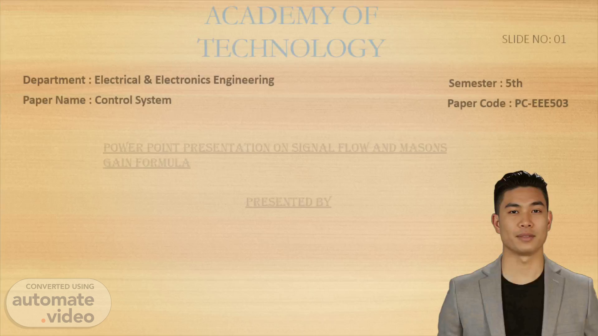
[Virtual Presenter] The slide number 1 of this presentation discusses the Department of Electrical and Electronics Engineering of Academy of Technology, the paper name of Control System and the name of the student who presented this Power Point Presentation, which is Kuntal Mistry. Kuntal Mistry has presented Signal Flow and Masons Gain Formula for the 5th Semester Electrical and Electronics Engineering course PC-EEE503 with this Power Point Presentation..
Page 2 (27s)
[Audio] We will be discussing Signal Flow Graphs (SFG), which are used to represent systems of interconnected components and show the flow of signals through those components. The two main topics we'll be taking a closer look at are the properties of Signal Flow Graphs, and the use of Mason's Gain Formula to reduce them. We will also explore the process of constructing SFGs for control systems, allowing us to construct complex systems through SFGs quickly and accurately..
Page 3 (57s)
[Audio] Signal-flow graphs offer a graphical approach to represent linear systems and networks. Through the process of constructing a signal-flow graph, Mason's Rules can be used to evaluate the associated network transfer functions and other related characteristics, which is applicable to analog, sampled-data, and digital systems and networks. These rules are named after American electronics engineer and MIT professor, Samuel Jefferson Mason..
Page 4 (1m 25s)
[Audio] The signal flow graph is a graphical representation of a control system which was developed by S J Mason. It’s a diagram that displays a collection of simultaneous linear algebraic equations which can be further converted into the s-domain. Through the use of the flow graph gain formula, the signal flow graph makes it easier to relate the input and output variables of a complex control system..
Page 5 (1m 51s)
[Audio] SFGs are used to describe linear systems and their cause and effect relationships. A node adds the signals of all incoming branches and the production of an outgoing signal can be treated as an output node by adding an outgoing branch with unity transmittance. If there is both incoming and outgoing signals, a mixed node can also be treated as an output node in the same way. Branches indicate the functional dependence of one signal on another, with signals travelling in only the designated direction and being multiplied by the gain or transmittance of the branch. It is important to note that the signal flow graph of a system is not unique and can be rearranged to draw a different signal flow graph for the same system..
Page 6 (2m 35s)
[Audio] For this slide, I am discussing the four rules for reducing a signal flow graph to obtain the transfer function. Rule 1 states that the incoming signal to a node is the product of the signal at the previous node and the gain of the branch. Rule 2 states that cascaded branches may be combined to give a single branch with transmittance equal to the product of individual branch transmittances. Rule 3 states that parallel branches may be represented by a single branch with transmittance being the sum of individual branch transmittances. Lastly, Rule 4 states that a mixed node can be eliminated by multiplying the transmittance of the outgoing branch to the transmittance of all incoming branches to the mixed node..
Page 7 (3m 20s)
[Audio] Mason's Gain Formula is an invaluable tool for simplifying signal flow graphs and computing the transfer function of a system. By drastically reducing the time and complexity of calculating the equations of the nodes and rearranging them to get the transfer function, it makes signal flow graph reductions far more feasible and efficient..
Page 8 (3m 40s)
[Audio] The Mason's gain formula can be used to calculate the transfer function of a control system through the signal flow graph. This formula states that the overall gain equals the determinant of the path multiplied by the path gain of each forward path. The determinant of the path is the sum of loop gains minus the sum of gain products of all possible combinations of two or more non-touching loops. To construct a signal flow graph, one must take the Laplace transform of the system's differential equations to obtain algebraic expressions in the s-domain, and then identify the constants and variables. To finish the task, the block diagram must be converted into a signal flow graph..
Page 9 (4m 24s)
[Audio] Mason's Gain Formula is a method of finding the transfer function of a control system by looking at its signal flow graph. It is used to determine the relationship between input and output and can be represented mathematically by the equation Delta = 1 - sum of individual loop gains + sum of gain products of all combinations of two non-touching loops - sum of gain products of all combinations of three non-touching loops and so on, with alternate change of signs. The equation Delta K gives the part of Delta which is not touching the Kth forward path..
Page 10 (4m 58s)
[Audio] This slide presents a list of suggested books for Control Systems study, as well as reliable links for additional reference. These books are: Control Systems Engineering by S K Bhattacharya, Modern Control Engineering by Katsuhiko Ogata, Instrumentation and Control Systems by K Padma Raju and Y J Reddy, Control Systems Engineering by D P Kothari and Advanced Control System Design by Bernard Friedland. Apart from these books, the slide also offers links to webpages that contain more information on Mason's Gain Formula and Signal Flow Graph, in case any further assistance is needed..
Page 11 (5m 37s)
[Audio] I greatly appreciate everyone taking the time to listen to my presentation and I hope you have found something useful in it. I enjoyed the opportunity to share my knowledge with you and I wish you all the best for the rest of the day. Thank you again for your attention..